Grønlandsudvalget 2013-14, Retsudvalget 2013-14
GRU Alm.del Bilag 14, REU Alm.del Bilag 35
Offentligt
Accident Investigation BoardDenmark
FINAL REPORTHCLJ510-000828HCLJ510-2011-43
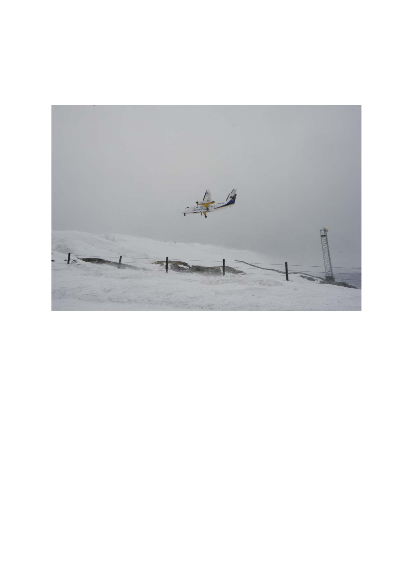
Accident to De Havilland DHC 8-106Registration TF-JMBNuuk Airport (BGGH), GreenlandThe 4thof March 2011
Page 1
============FOREWORD============
This report reflects the opinion of the Accident Investigation Board Denmark regarding thecircumstances of the accident and its causes and consequences.In accordance with the provisions of the EU Regulation 996/2010 and pursuant to the Annex13 of the International Civil Aviation Convention, the investigation is of an exclusivelytechnical and operational nature, and its objective is not the assignment of blame or liability.The investigation was carried out without having necessarily used legal evidence proceduresand with no other basic aim than that of preventing future accidents.Consequently, any use of this report for purposes other than preventing future accidents maylead to erroneous or misleading interpretations.
Page 2
Table of contentsSYNOPSIS ............................................................................................................................................................. 61.1.11.21.31.41.51.5.11.5.21.61.6.11.6.21.6.31.6.41.71.7.11.7.21.7.31.7.41.7.51.7.61.7.71.81.8.11.8.21.91.9.11.9.21.9.11.10FACTUAL INFORMATION ................................................................................................................. 7HISTORY OF THE FLIGHT.................................................................................................................... 7INJURIES TO PERSONS...................................................................................................................... 10DAMAGE TO AIRCRAFT.................................................................................................................... 10OTHER DAMAGE.............................................................................................................................. 10PERSONNEL INFORMATION............................................................................................................... 10The commander .............................................................................................................................. 10The first officer ............................................................................................................................... 12AIRCRAFT INFORMATION................................................................................................................. 14General ........................................................................................................................................... 14Airworthiness and maintenance ...................................................................................................... 14Main landing gear system ............................................................................................................... 14Crosswind limitations ..................................................................................................................... 16METEOROLOGICAL INFORMATION.................................................................................................... 17General ........................................................................................................................................... 17Wind at the BGGH area.................................................................................................................. 17SIGMET ......................................................................................................................................... 18METAR .......................................................................................................................................... 18TAF ................................................................................................................................................ 19SIGWX FL050-FL280 ................................................................................................................... 20Wind/Temperature FL050 .............................................................................................................. 20AIDS TO NAVIGATION....................................................................................................................... 21LLZ/DME RWY 23 ........................................................................................................................ 21Operator’s instrument approach chart – runway 23 ........................................................................ 22COMMUNICATION............................................................................................................................ 23General ........................................................................................................................................... 23Sondrestrom FIC............................................................................................................................. 23Nuuk AFIS ...................................................................................................................................... 23AERODROME INFORMATION............................................................................................................. 23
1.10.1 BGGH aerodrome ........................................................................................................................... 231.10.2 Terrain surrounding BGGH ............................................................................................................ 241.10.3 Final approach track ....................................................................................................................... 251.11FLIGHT RECORDERS......................................................................................................................... 251.11.1 FDR and CVR time reference ......................................................................................................... 251.11.2 Flight Data Recorder (FDR) ........................................................................................................... 261.11.3 Cockpit Voice Recorder (CVR)...................................................................................................... 261.11.4 Quick Access Recorder (QAR)....................................................................................................... 26
Page 3
1.12
WRECKAGE AND IMPACT INFORMATION........................................................................................... 26
1.12.1 General ........................................................................................................................................... 261.12.2 Fuse pin analysis ............................................................................................................................. 301.12.3 The touchdown ............................................................................................................................... 321.12.4 Vertical acceleration ....................................................................................................................... 331.12.5 Rate of descent................................................................................................................................ 331.12.6 Lateral acceleration......................................................................................................................... 341.12.7 Bank angle ...................................................................................................................................... 341.12.8 Magnetic heading............................................................................................................................ 341.12.9 Pitch attitude ................................................................................................................................... 351.12.10 Calibrated airspeed (CAS) .............................................................................................................. 351.12.11 Engine torque.................................................................................................................................. 351.131.141.15MEDICAL AND PATHOLOGICAL INFORMATION.................................................................................. 36FIRE................................................................................................................................................. 36SURVIVAL ASPECTS.......................................................................................................................... 36
1.15.1 Acceleration .................................................................................................................................... 361.15.2 Cockpit and cabin structure ............................................................................................................ 361.15.3 Seats and seatbelts .......................................................................................................................... 361.15.4 Exposure ......................................................................................................................................... 371.15.5 Injuries ............................................................................................................................................ 371.15.6 Evacuation ...................................................................................................................................... 371.161.171.18TESTS AND RESEARCH..................................................................................................................... 38ORGANIZATIONAL AND MANAGEMENT INFORMATION...................................................................... 38ADDITIONAL INFORMATION............................................................................................................. 39
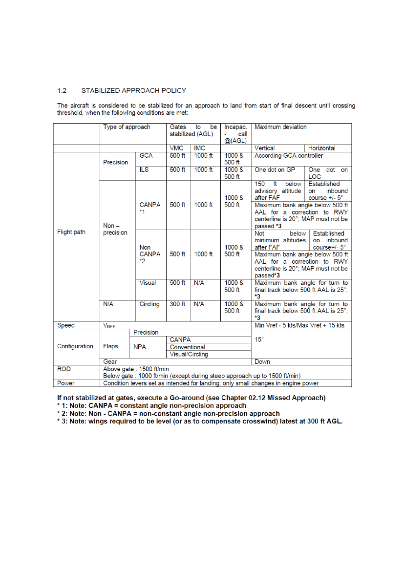
1.18.1 VMC approaches to runway 23 ...................................................................................................... 391.18.2 BGGH aerodrome and procedure briefing...................................................................................... 391.18.3 Stabilized approach policy.............................................................................................................. 391.192.2.12.22.33.3.13.23.34.4.14.2USEFUL OR EFFECTIVE INVESTIGATION TECHNIQUES........................................................................ 39ANALYSIS ............................................................................................................................................ 39General .......................................................................................................................................... 39Flight planning and enroute ........................................................................................................... 39Approach to BGGH ....................................................................................................................... 40CONCLUSIONS ................................................................................................................................... 41Findings ......................................................................................................................................... 41Factors ........................................................................................................................................... 41Summary ........................................................................................................................................ 42SAFETY RECOMMENDATIONS ..................................................................................................... 42Safety recommendation ................................................................................................................. 42Preventive actions .......................................................................................................................... 42
Page 4
5.
APPENDICES ....................................................................................................................................... 43APPENDIX1 –APPROACH AND LANDING............................................................................................................ 44APPENDIX2 – FDRPLOTS.................................................................................................................................. 60The approach ................................................................................................................................................ 60The landing ................................................................................................................................................... 61Longitudinal controls.................................................................................................................................... 62Lateral and directional controls .................................................................................................................... 63Engines and propellers ................................................................................................................................. 63Navigation .................................................................................................................................................... 65APPENDIX3 – BGGHAERODROME AND PROCEDURE BRIEFING......................................................................... 66APPENDIX4 – STABILIZED APPROACH POLICY.................................................................................................... 70
Page 5
FINAL REPORTHCLJ510-000828HCLJ510-2011-43Aircraft:Engines:Crew:Place:AccidentDe Havilland DHC 8-1062 – P & W 1213 – no injuriesRunway 23 at Nuuk,Greenland (BGGH)Registration:Flight:Passengers:Date & Time:TF-JMBCommercial flight, IFR31 - no injuries4.3.2011 at 16:09 hrs. UTC
All time references are UTC.SynopsisOn 4.3.2011 at 16:30 hrs, the Danish Accident Investigation Board (AIB) was notified of the accident bythe Danish Transport Authority. Within the following hours, the notifications from Nuuk Airport, the Policeand the Area Control Centre (ACC) Copenhagen were received.The Canadian Transportation Safety Board (TSB), the Icelandic Aircraft Accident Investigation Board(AAIB), the European Aviation Safety Agency (EASA), the European Commission and the InternationalCivil Aviation Organization (ICAO) were notified on 4.3.2011.The investigation was conducted by the AIB in close cooperation with the AAIB and the TSB.The accident flight was a commercial passenger flight from Reykjavik Airport, Iceland (BIRK) to NuukAirport, Greenland (BGGH).At Kulusuk, Greenland (BGKK), the flight made a technical landing and uplifted fuel.The flight crew got visual contact with the runway at BGGH and decided to deviate to the right (west) ofthe offset localizer (LLZ) to runway 23. The flight continued towards the runway from a position right ofthe extended runway centerline. As the aircraft approached runway 23, it was still in the final right turnover the landing threshold. The aircraft touched down on runway 23 between the runway threshold and thetouchdown zone and to the left of the runway centerline. The right main landing gear (MLG) shock strutfuse pin sheared leading to a right MLG collapse. The aircraft skidded down the runway and departed therunway to the right.Neither passengers nor crew suffered any injuries. The aircraft was substantially damaged.The accident occurred in daylight under visual meteorological conditions (VMC).The investigation has not resulted in any recommendations being made.
Page 6
SummaryAdverse wind and turbulence conditions at BGGH led to flight crew task saturation on final approach and abreakdown of optimum cockpit resource management (CRM) resulting in a divergence from the operator’sstabilized approach policy.The divergence from the operator’s stabilized approach policy caused an unstabilized approach and a hardlanding leading to an excess load of the right MLG at touchdown.According to its design, the right MLG fuse pin sheared as a result of stress.1.Factual information1.1History of the flightAt 12:49/12:52 hrs, the flight made a technical landing and uplifted fuel at BGKK.The flight was scheduled to depart BGKK at 13:05 hrs and to arrive at BGGH at 15:00 hrs.Due to the weather conditions at BGGH, the flight crew decided to delay the departure from BGKKand await an improvement of the weather at BGGH.The flight departed BGKK at 14:13/14:17 hrs. The commander was the pilot flying (PF) and the firstofficer was the pilot not flying (PNF). With reference to the filed ATS flight plan, the destination alternateaerodrome was Kangerlussuaq (BGSF).Enroute, the flight crew got the following BGGH weather information from Sondrestrom Flight InformationCentre (FIC):14:23 hrs: Wind 150�/32 knots maximum 42 knots variable between 130� and 190�. Visibility 6kilometers in light showers of snow with blowing and drifting snow.15:39 hrs: Wind 160�/33 knots maximum 48 knots. Visibility 3000 meters in snow with patches of fog,low drifting snow, few clouds at 1600 feet, broken clouds at 2800 feet, temperature minuszero, dew point minus four and QNH 1015 hPa.The FIC informed the flight crew that only one aircraft had departed BGGH and only oneaircraft had landed at BGGH since the beginning of airport operation that day.15:42 hrs: SIGMET issued for the west coast of Greenland:The SIGMET was affecting a part of Nuuk Traffic Information Zone (TIZ). Severeturbulence was forecasted from the surface to 8000 feet. The turbulence was stationary andthere was not forecasted any change.Page 7
15:44 hrs: Update on turbulence information:It was stretching from the surface to 7000 feet and it was weakening.During decent to BGGH, the flight crew discussed the approach, the present crosswind conditions and theconsequential operational effects.Due to the wind conditions at BGGH, the flight crew agreed on using a final flap setting of 15� instead of aflap setting of 35�. Furthermore, they agreed on flying the aircraft at an airspeed “on the high side”, flyingthe approach to the right of the offset localizer (LLZ) at a high altitude and at a steep approach angle andfinally not aiming too close to the runway end.When in radio contact with Nuuk AFIS, the flight crew got the following weather information:15:57 hrs: Runway in use 23. Wind 180� (magnetic)/29 knots maximum 43 knots. QNH 1014 hPa.Temperature zero degrees. 25% of the runway covered with up to one mm compacted snow.50% of the runway covered with loose fine snow. Braking action measured with a TapleyDecelerometer. Braking action on runway 23 55-55-50.15:58 hrs: Runway in use 23. Wind 170� (magnetic)/24 knots maximum 43 knots. Visibility 4000meters in light snow, moderate blowing snow. Few clouds at 1800 feet, broken clouds at3500 feet. Temperature zero degrees. Dew point minus four. QNH 1014 hPa.During decent passing through approximately 5000 feet, the flight crew got visual contact with the groundand shortly after (passing through approximately 4500 feet), the landing gear was selected down.The flight crew got visual contact with the runway and a deviation to the right (west) of the offset LLZ torunway 23 was initiated (visual approach).The flight crew observed how the wind changed the surface of the sea (ripples) and that the wind appearedto be calmer to the right of the offset LLZ. For that reason, the flight crew planned to avoid overflying areasof sea ripples.As the aircraft came closer to the airport, the PNF pointed out areas on the surface of the sea with lessripples. It formed a “passage” to the airport (also referred to as “a worm”). The flight crew decided tofollow “the worm”.The autopilot was disengaged.
Page 8
Shortly after and in a left turn at approximately 1912 feet radio altimeter (RA), flap setting 15� wasselected. The calibrated airspeed (CAS) decreased from 140 knots to 110 knots. During the decrease of theCAS, the engine toque remained below 10%. At the same time, the PF called for the condition levers tomaximum setting. The propeller RPM increased from approximately 1,050 to 1,200 RPM.The flight continued towards the runway threshold from a position right of the runway centerline. The PFaimed to land the aircraft at a point between the runway threshold and the touchdown zone.At 1485 feet RA, the “before landing checklist” was performed. The landing reference airspeed (Vref) was102 knots and the target airspeed (Vtgt) was 117 knots.When the aircraft was on a 3 nm final to runway 23, Nuuk AFIS reported that there was no traffic onrunway 23 and the wind direction was 180� (magnetic), the wind speed was 17 knots maximum 42 knotsand the wind direction was variable between 140� (magnetic) and 220� (magnetic).The flight crew started discussing the use of flap setting and agreed on using flaps 35� as final flap setting.The Vref was changed to 92 knots and the Vtgt was changed to 107 knots.While the aircraft was tracking for the threshold to runway 23, it entered an area with moderate to severeturbulence.Flap setting 35� was selected and while the aircraft was descending through approximately 711 feet RA.In landing configuration, the aircraft approached the runway at a lateral angle of approximately 25�. Theaircraft was heading towards the landing threshold runway 23.The aircraft initiated a right turn from magnetic heading 195� towards the runway heading of 228.5�(MAG). The CAS was 115 knots decreasing and the RA was 144 feet. The rate of descent wasapproximately 780 feet per minute. The pitch attitude was approximately -5�.As the aircraft approached the runway and crossed the threshold to runway 23, the bank angle wasapproximately 10� to the right increasing momentarily to 18�. The aircraft overshot the runway centerline tothe left. The engine torque was approximately 20%.The pitch attitude increased from -6� to -3� and prior to touchdown to +0.9�. The average rate of descentwas approximately 13.5 feet per second (810 fpm).The aircraft touched down on runway 23 between the runway threshold and the touchdown zone and to theleft of the runway centerline. The aircraft touched down on the right main landing gear (MLG) with acrosswind from the left. The aircraft was banking more than 12� to the right as the aircraft touched down.Page 9
At touchdown, the vertical acceleration was approximately 3.9 G. The CAS was approximately 85 knots.The right MLG shock strut fuse pin sheared leading to a right MLG collapse.The aircraft skidded down the runway and departed the runway to the right.The nose landing gear separated from the aircraft as the aircraft entered the unpaved area to the right of therunway.The aircraft came to rest in a rocky area just outside the runway safety zone to the right of runway 23.For a further presentation on the approach and landing – see appendix 1.Throughout the final approach, no flight crew call outs on stabilized approach were made.The passengers and crew evacuated the aircraft using the forward right emergency exit (service door).1.2Injuries to personsCrewPassengersOther
InjuriesFatalSeriousMinor/None
3
31
1.3Damage to aircraftThe aircraft was substantially damaged.1.4Other damageThere were minor dents in the runway. One runway edge light was destroyed.1.5Personnel information1.5.1The commander1.5.1.1 License and ratingsThe commander was the holder of an ATPL (A) initially issued on 28.1.2003.The license contained the following type ratings: DHC-6, F50 and DHC-8.The type rating on DHC-8 was issued 25.1.2011.
Page 10
The DHC-8 proficiency check was passed on the 25.1.2011 (Pilot in Command).The date of last medical approval was 21.4.2010. There were no medical limitations.1.5.1.2Flying experienceLast 24 hours2.92.92Last 90 days44.644.632Total8,163.644.6
All typesThis typeLandings this type
1.5.1.3
Duty timeTime betweenduty’s (H)
The commander
Check in22.2.2011 08:3024.2.2011 10:4525.2.2011 10:0026.2.2011 11:151.3.2011 08:302.3.2011 08:304.3.2011 09:30
Check out22.2.2011 20:2624.2.2011 20:3025.2.2011 22:0826.2.2011 17:081.3.2011 14:002.3.2011 20:064.3.2011 22:00
Duty hours11.9338.329.7513.5012.1313.125.88111.375.5018.5011.6037.4012.50
1.5.1.4 Observation Flight LogThe Observation Flight Training Log from 12.12.2010 to 23.12.2010 had 11 entries. There were two flightsto and from Nuuk (BGGK), Greenland.1.5.1.5 Line Flight Training LogThe Line Flight Training Log from 28.1.2011 to 26.2.2011 had 30 entries. There were two flights to andfrom Kulusuk (BGKK), Greenland. The rest of the flights were domestic within Iceland.
Page 11
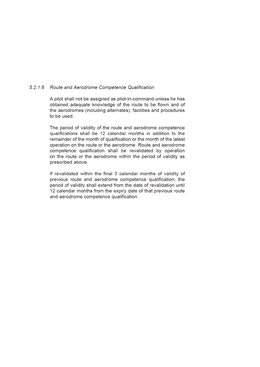
1.5.1.6 Line CheckThe commander was released for continuous line duty on 26.2.2011. The flight was from BIRK to BGKKto BIRK.1.5.1.7 Route and aerodrome competence qualificationExtract from the operator’s Operations Manual Part A
1.5.2The first officer1.5.2.1 License and ratingsThe first officer was the holder of an ATPL (A) initially issued on 15.4.2008.The license contained the following type rating: DHC-8.The type rating on DHC-8 was issued on 2.5.2010.The DHC-8 proficiency checks were passed on 16.10.2009, 2.5.2010 and 13.10.2010 (Co-pilot).The date of last medical approval was 13.7.2010. There were no medical limitations.
Page 12
1.5.2.2
Flying experienceLast 24 hours6.06.02Last 90 days26.126.18Total4567.11130280
All typesThis typeLandings this type1.5.2.3Duty time
The first officer
Time betweenduty’s (H)Check out27.2.2011 21:211.3.2011 05:412.3.2011 14:303.3.2011 20:204.3.2011 22:00Duty hours5.3521.4010.9332.320.5018.0011.8313.1712.50
Check in27.2.2011 16:0028.2.2011 18:452.3.2011 14:003.3.2011 08:304.3.2011 09:30
1.5.2.4 Observation Flight LogThe Observation Flight Training Log from 2.3.2008 to 17.3.2008 had 16 entries. The flights were domesticwithin Iceland.1.5.2.5 Line Flight Training LogThe Line Flight Training Log from 17.4.2008 to 5.5.2008 had 32 entries. There were three flights to andfrom Kulusuk (BGKK), Greenland. The rest of the flights were domestic within Iceland.1.5.2.6 Line CheckThe first officer was released for continuous line duty on 25.7.2010. The flight was from BIRK to BIEG toBIRK.
Page 13
1.61.6.1
Aircraft informationGeneralTF-JMBDash-8106Bombardier Aerospace, Canada3371992Pratt & Whitney CanadaPW 121Two variable pitch32 336:4935 300MZFW:MTOW:MLW:14 515 Kg. (32 000 lbs.)16 466 Kg. (36 301 lbs.)15 377 Kg. (33 900 lbs.)
Registration:Type:Model:Manufacturer:Serial number:Year of manufacture:Engine manufacturer:Engines type:Propellers:Aircraft total flight hours:Aircraft total flight cycles:ZFW:TOW:LW:13 865 Kg.16 235 Kg.15 135 Kg.
Centre of Gravity (% MAC):At TOWAt ZFW34.3234.16FWD limit 22.40FWD limit 18.35AFT limitAFT limit37.7639.61
Note: Before LMC.The aircraft was within the mass and centre of gravity limitations.1.6.2Airworthiness and maintenanceThe airplane maintenance records were verified to be in compliance with the established maintenanceprogram and the airworthiness certificate was valid.The flight logbook had no abnormal records.1.6.3Main landing gear system1.6.3.1 General descriptionThe retractable landing gear consisted of two main gear assemblies, one mounted in each nacelle under thewings, and a nose gear assembly mounted in a well in the front fuselage.
Page 14
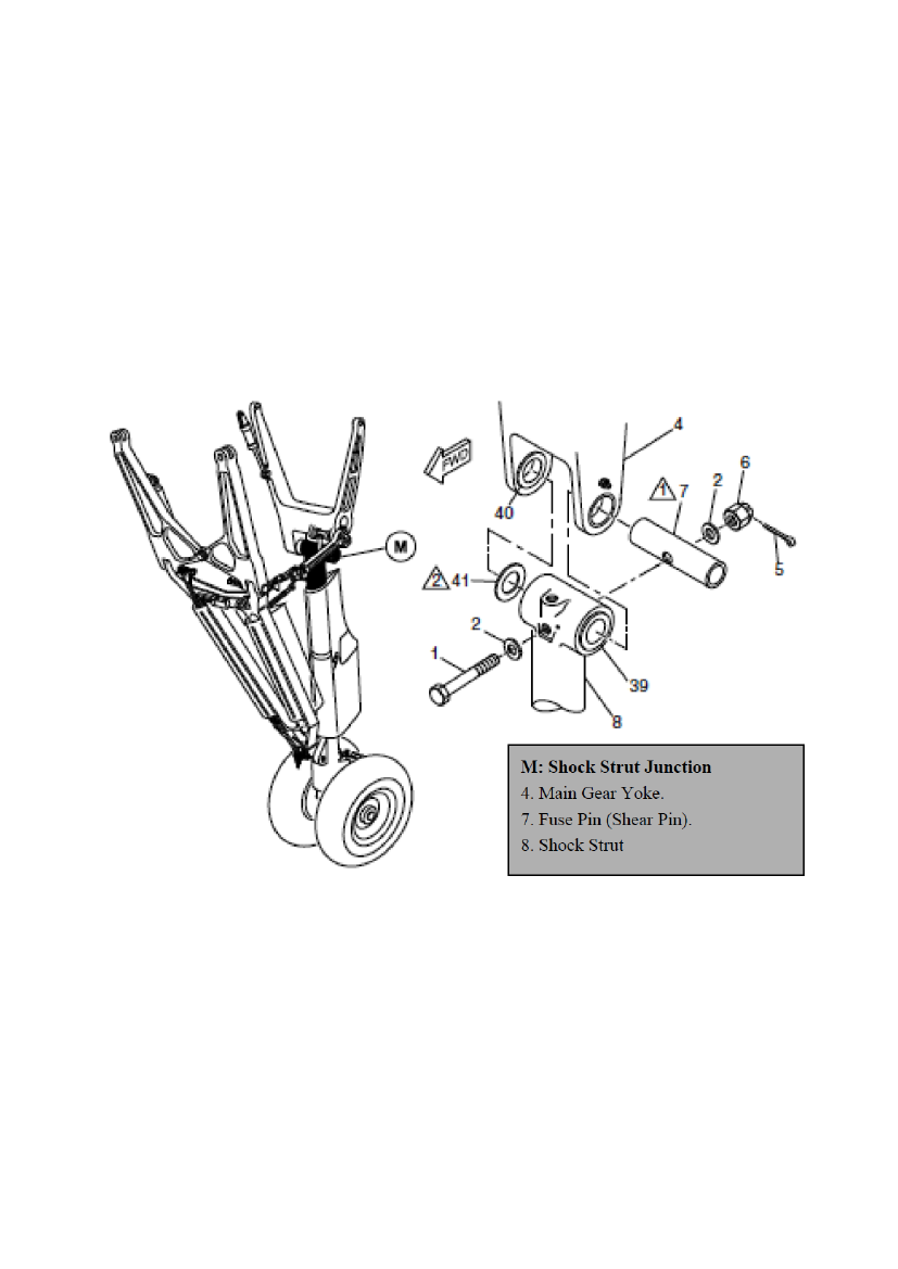
Both the main and the nose gear assemblies incorporated shock struts and dual wheels were fully enclosedby doors when retracted.The main gear assemblies retracted rearward and the nose gear assembly retracted forward; normalextension and retraction were hydraulically actuated.1.6.3.2 Fuse pin and Joint Aviation (JAR) requirementTo prevent the gear from rupturing the fuel tanks inside the wing box during a rough landing, a fuse pin(shear pin) was installed at each main landing gear yoke to shock strut junction. This was to comply withJAR 25.721(a) and JAR 25.963(d). The purpose of those JAR requirements was to demonstrate adequateairframe strength (especially of the wing in the fuel tank zones) up until the instant where breakage of thefuse pin occurs.
1.6.3.3 Main landing gear structural fuse pin p/n 10150-5The structural fuse pin was designed to shear if the aircraft touched down in level attitude at a rate of decentof more than 894 to 942 feet per minute – or if - the aircraft touched down in a tail down attitude at a rate ofdecent of more than 996 to 1029 feet per minute.
Page 15
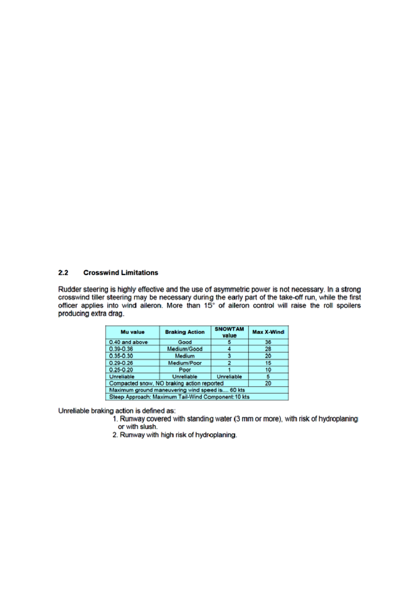
The preconditions for those figures were landing on both MLG simultaneously at the maximum landingweight (MLW) and without any sideways movement.In the manufacturer’s maintenance program the fuse pin p/n 10150-5 had a life limit of 24 240 flights(Cycles) and did not contain periodic inspections.At the time of the accident, the fuse pin p/n 10150-5 with serial number EXC5334 installed on the rightMLG had 6 197 cycles. The remaining cycles were 18 043.1.6.3.4 Maintenance ManualThe aircraft Maintenance Manual definition of a landing at a vertical decent rate greater than 600 feet perminute when the aircraft gross weight was less than or equal to MLW was a hard landing.This would always require an inspection of the aircraft especially an inspection of the main landing gearsystem.1.6.4Crosswind limitationsExtract from the Airplane Operating Matters (AOM)
Page 16
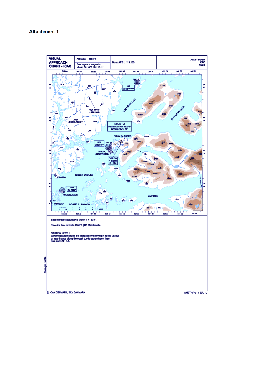
1.7Meteorological information1.7.1GeneralNo telephone weather briefing related to the flight was recorded.A deep low was situated south of Greenland and a trough was situated in the Davis Strait. A minor low (dueto lack of observations not possible to estimate the centre pressure) was located just west of BGGH and wasmoving slowly north.These lows were rather common and were known to produce high winds in the BGGH-area, mostly causedby the orography around BGGH where the icecap and the mountains “Lille Malene” and “Store Malene”caused wind convergence, especially near the aerodrome.The aerodrome wind was known to be higher than the wind recorded in Nuuk city.Weather:Visibility:Clouds:Light snow and drifting/blowing snow2500-6000 meters in snow, tempo 0800-2000 meters in blowing snowSct/bkn 1400-1600 feet and bkn 3500 feet. Cloud tops unknownThe vertical visibility in blowing snow was 0800-1200 feetIcing:QNH:Light/moderate in clouds1015 hPa
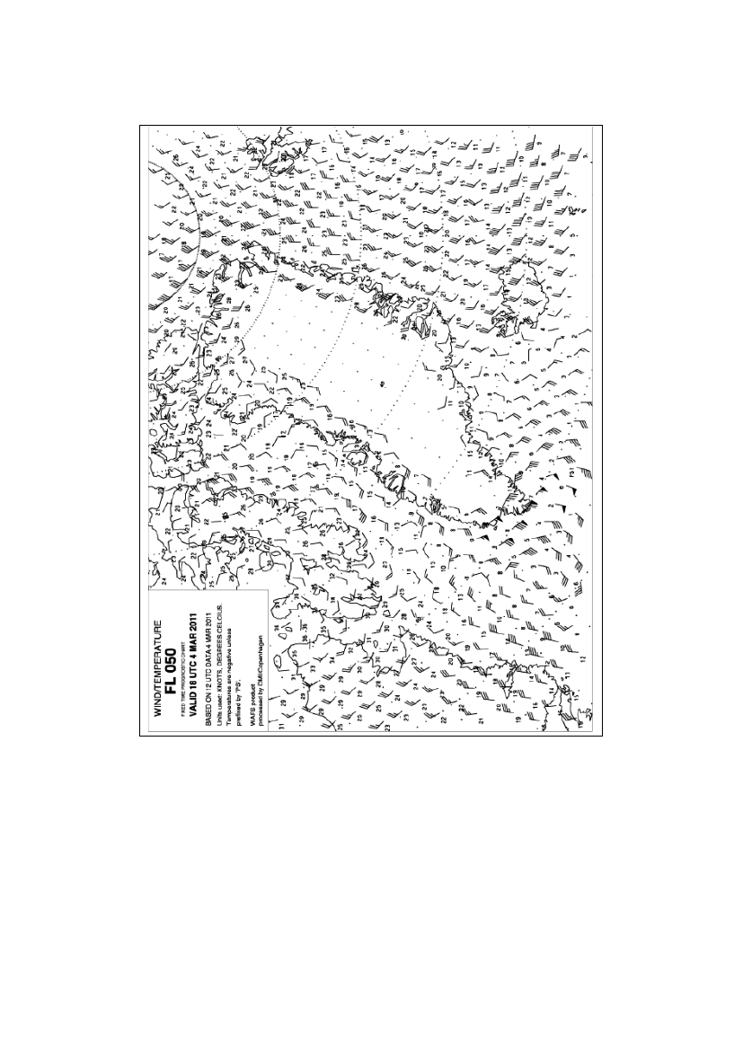
1.7.2Wind at the BGGH area(All directions are TRUE)The surface winds were strong and gusty. Direction 150-160 degrees, 28-35 knots with gusts to 40-43knots.Due to the complex terrain around BGGH and the lack of sounding (RAOB) observations, it was verydifficult to estimate the wind variation with altitude.Model-Forecasts (not WAFS but a DMI Hirlam-model) indicated a 50 knots wind at 5000 feet.The wind variation at 5000 feet-SFC could not be estimated or described in any reliable form.Due to the orography, the wind at 5000-3000 feet would have been more or less laminar, but with somevariations in direction and airspeed during approach (wind shear).Page 17
Below 3000 feet the flow would most likely have been less laminar and more gusty and turbulent.The wind and turbulence conditions would most likely have been significantly different south of the field.These estimated winds below 2000 feet are highly theoretical and should be used with limited confidence:2000 feet:1500 feet:1000 feet:0500 feet:0100 feet:160� 40 knots gusting to 50 knots160� 35 knots gusting to 50 knots160� 35 knots gusting to 50 knots150� 30 knots gusting to 45 knots150� 30 knots gusting to 45 knots
Wind shears and turbulence below 5000 feet would have been significant (at least moderate).1.7.3SIGMETAt the time of the accident, there was no valid SIGMET for the Nuuk area.A SIGMET was issued at 12:33 hrs:BGGL SIGMET 2 VALID 041235/041515 BGSF - BGGL SONDRESTROM FIR SEV TURB FCSTALONG SW-COAST OF GREENLAND BTN N6315 AND N6415 SFC/FL070 STNR WKN=1.7.4BGGH041250 METAR041255 SPECI041350 METAR041420 SPECIbggh 041250z 16032g44kt 0800 sn blsn drsn vv010 m00/m04 q1016=bggh 041255z 16035g55kt 0800 sn blsn drsn vv010 m00/m03 q1016=bggh 041350z 15036g56kt 2500 -sn blsn drsn bkn014 m00/m03 q1015=bggh 041420z 15032g42kt 120v190 6000 -shsn blsn drsn bkn015 m00/m04q1016=bggh 041450z 16033g48kt 3000 -sn bcfg drsn few016 bkn028 m00/m04q1015=METAR
041450 METAR
Page 18
041550 METAR041650 METAR
bggh 041550z 16028g40kt 4000 -sn few018 bkn035 00/m05 q1015=bggh 041650z 16019kt 130v190 9999 -sn few018 bkn030 01/m01 q1014 rmkad closed=
BGSF041250 METAR041350 METAR041450 METAR041550 METAR041650 METARbgsf 041250z 07004kt 9999 few080 m03/m09 q1020=bgsf 041350z 08007kt 9999 few050 m03/m09 q1019=bgsf 041450z 06006kt 020v090 9999 few050 m05/m10 q1019=bgsf 041550z 05007kt 9999 few050 bkn200 m05/m09 q1018=bgsf 041650z 06006kt 9999 sct150 bkn200 m03/m08 q1017=
1.7.5BGGH
TAF
040900 TAF-FC
bggh 040920z 0409/0418 36008kt 3000 -sn bkn015 tempo 0409/041807008kt 0500 sn vv004=bggh 041020z 0410/0419 36008kt 3000 -sn bkn015 tempo 0410/041907008kt 0500 sn vv004=
041000 TAF-FC
041000 TAF-FC COR bggh 041020z 0410/0419 36008kt 5000 -sn bkn015 tempo 0410/041707008kt 0500 sn vv004 tempo 0417/0419 2000 vv008=041000 TAF-FC AMD bggh 041200z 0412/0419 10015kt 0400 +sn blsn vv004 tempo 0412/041517025g38kt 4000 -sn drsn bkn010 becmg 0415/0417 14012kt 9999 nswbkn018 tempo 0417/0419 2800 -sn vcsh bkn012=041000 TAF-FC AMD bggh 041230z 0412/0419 15032g55kt 0400 +sn blsn vv002 tempo 0412/041517020kt 4000 -sn drsn bkn010 becmg 0415/0417 14012kt 9999 nsw bkn018tempo 0417/0419 2800 -sn vcsh bkn012=041300 TAF-FCbggh 041300z 0413/0422 15032g55kt 0400 +sn blsn vv002 tempo 0413/041615025g38kt 4000 -sn vv015 becmg 0416/0418 14012kt 9999 nsw bkn018tempo 0418/0422 2800 -sn vcsh bkn012=Page 19
041300 TAF-FC AMD bggh 041425z 0414/0422 16032g48kt 1200 sn blsn vv002 tempo 0414/041612022g35kt 8000 -sn drsn bkn018 becmg 0416/0418 14012kt 9999 nswbkn018 tempo 0418/0422 2800 -sn vcsh bkn012=041600 TAF-FCbggh 041600z 0416/0501 16028g40kt 3000 -sn drsn sct015 bkn030 becmg0417/0419 15018kt 9999 nsw tempo 0419/0501 vrb10kt 2800 -sn vcshbkn012=
BGSF040500 TAF-FT041100 TAF-FTbgsf 040500z 0406/0506 06010kt 9999 bkn120 tempo 0406/0506 12018kt=bgsf 041100z 0412/0512 08012kt 9999 bkn150 tempo 0417/0423 12018ktdrsn becmg 0423/0501 12018kt drsn tempo 0501/0512 16020g38kt=
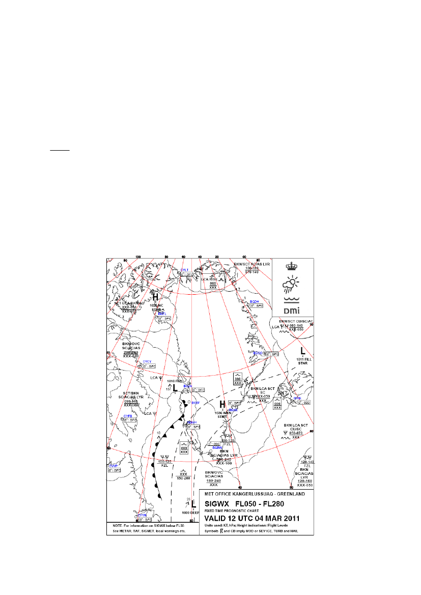
1.7.6
SIGWX FL050-FL280
Page 20
1.7.7
Wind/Temperature FL050
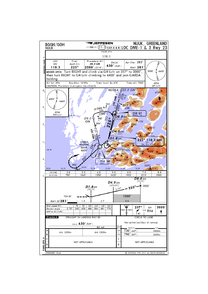
1.8Aids to navigation1.8.1LLZ/DME RWY 23The instrument approach procedure in use by the flight crew was the LLZ/DME RWY 23. The approachprocedure was based on the LLZ GN 110.300 MHz and the co-located DME GN CH 40x.At the time of the accident there were no reports concerning unserviceable approach aids to navigation atBGGH.Page 21
1.8.2
Operator’s instrument approach chart – runway 23
Page 22
1.9Communication1.9.1GeneralThe flight crew was in VHF radio contact with Kulusuk AFIS, Sondrestrom FIC and Nuuk AFIS.1.9.2Sondrestrom FICThe radio communication between the flight crew and Sondrestrom FIC (121.300 MHz) was recorded. TheDK AIB obtained a copy of the recording. The recording was of good quality and was useful to theinvestigation.1.9.1Nuuk AFISThe radio communication between the flight crew and Nuuk AFIS (119.100 MHz) was recorded. The DKAIB obtained a copy of the recording. The recording was of good quality and was useful to theinvestigation.1.101.10.1Aerodrome informationBGGH aerodrome
Aerodrome position (ARP):Elevation:Magnetic variation:Runway identifications:Direction of runway 23:SurfaceRunway dimensions:“Strip” dimensions:
64� 11’ 27.32N 51� 40’ 41.03E283 feet30 W (January 2009)RWY 05 and RWY 23198.5� (GEO) and 228.5� (MAG)Asphalt950 x 30 meters1010 x 100 meters. This area was paved (smooth). Therunway was located in the center of the “strip”. Outsidethe “strip”, the area was rocky and unpavedPrecision Approach Path Indicator (PAPI):A PAPI to runway 23 was located approximately at thetouchdown zone. The angle was 3�.Landing distance available – RWY 23 (LDA): 950 metersRescue and firefighting ServiceCAT 5
Page 23
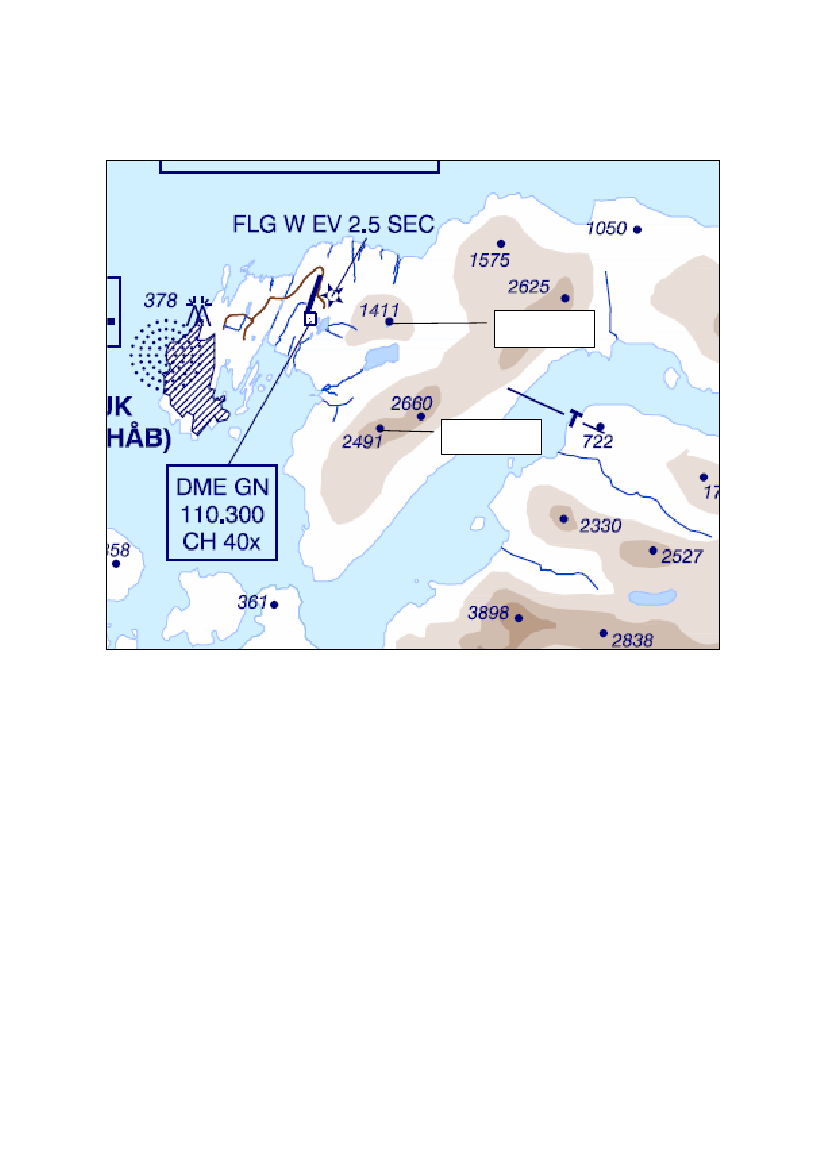
1.10.2
Terrain surrounding BGGH
Lille Malene
Store Malene
NoteThe AIB has changed the scale of the AIP map and inserted the names of the mountains “Store Malene”and “Lille Malene”.
Page 24
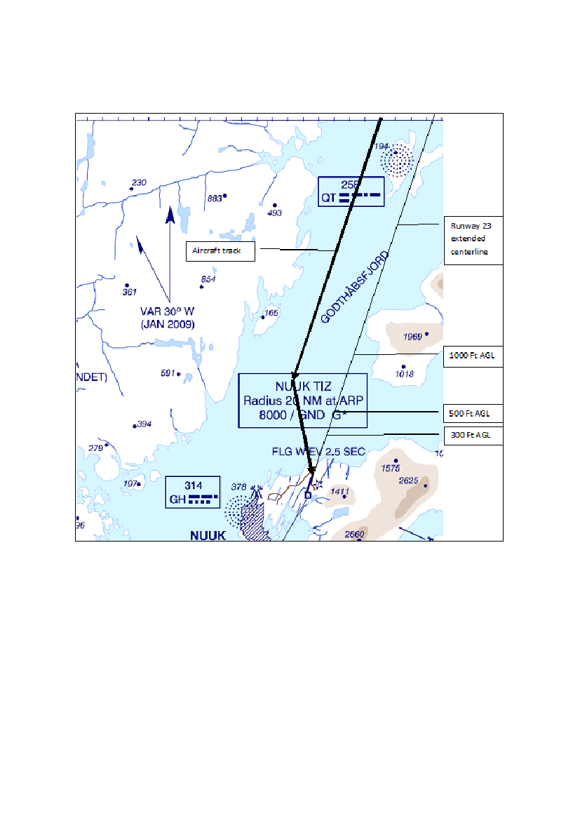
1.10.3
Final approach track
NoteThe AIB has changed the scale of the AIP map and inserted the aircraft approach track. The extendedcenterline of runway 23 is inserted with the associated 3� approach angle heights above TDZ elevation.1.11Flight recorders1.11.1 FDR and CVR time referenceThe time reference used in the FDR and CVR recorded data was “relative time” and not UTC.The time of the accident (16:09 hrs) was determined from the recorded radio communication between NuukAFIS and aircraft/vehicles.Page 25
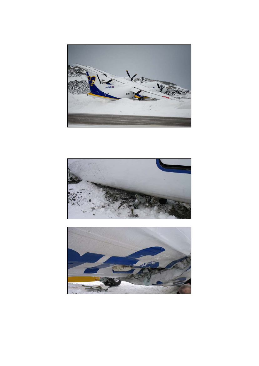
The recorded “relative time” used by the FDR and CVR was transformed into UTC using the significantevent recorded on the FDR and CVR.1.11.2 Flight Data Recorder (FDR)Shortly after the accident, the FDR was removed from the aircraft.The recorder appeared undamaged.The FDR was a Solid State Flight Data Recorder (SSFDR). The FDR data were retrieved and were usefulto the investigation.See appendix 2 – FDR plots.1.11.3 Cockpit Voice Recorder (CVR)Shortly after the accident, the CVR was removed from the aircraft.The recorder appeared undamaged.The CVR was a Solid State Cockpit Voice Recorder (SSCVR). The CVR data were retrieved and wereuseful to the investigation.1.11.4 Quick Access Recorder (QAR)Shortly after the accident, the QAR data chip was removed from the aircraft.The retrieved data contained only engine parameters and were useful to the investigation.1.12Wreckage and impact information1.12.1 GeneralAt touchdown on runway 23, the right main landing gear collapsed. Immediately hereafter, the right winghit the runway.At first, the aircraft veered to the right and seconds later to the left. The aircraft departed the runway to theright into rocks.The outer third of all four right propeller blades were cut off, when the blades made contact with therunway.The right nacelle, the right wing, the flaps and aileron were damaged as a result of the runway contact.
Page 26
The right main landing gear was substantially damaged due to the collapse of the gear.
As a result of hitting the rocks, the nose landing gear was destroyed and the aft fuselage sufferedsubstantially damage.
Page 27
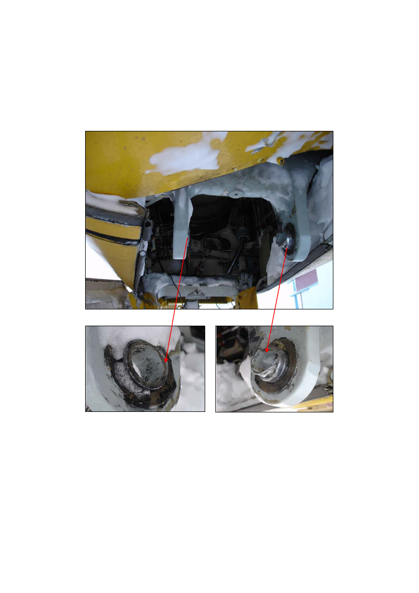
The fuse pin of the right main landing gear was found sheared at two places.Both ends of the fractured fuse pin were found at place in the junction.Due to fracture of the fuse pin, the shock strut was separated from the main gear yoke.
Page 28
The rest of the fuse pin was found inside the head of shock strut to yoke.
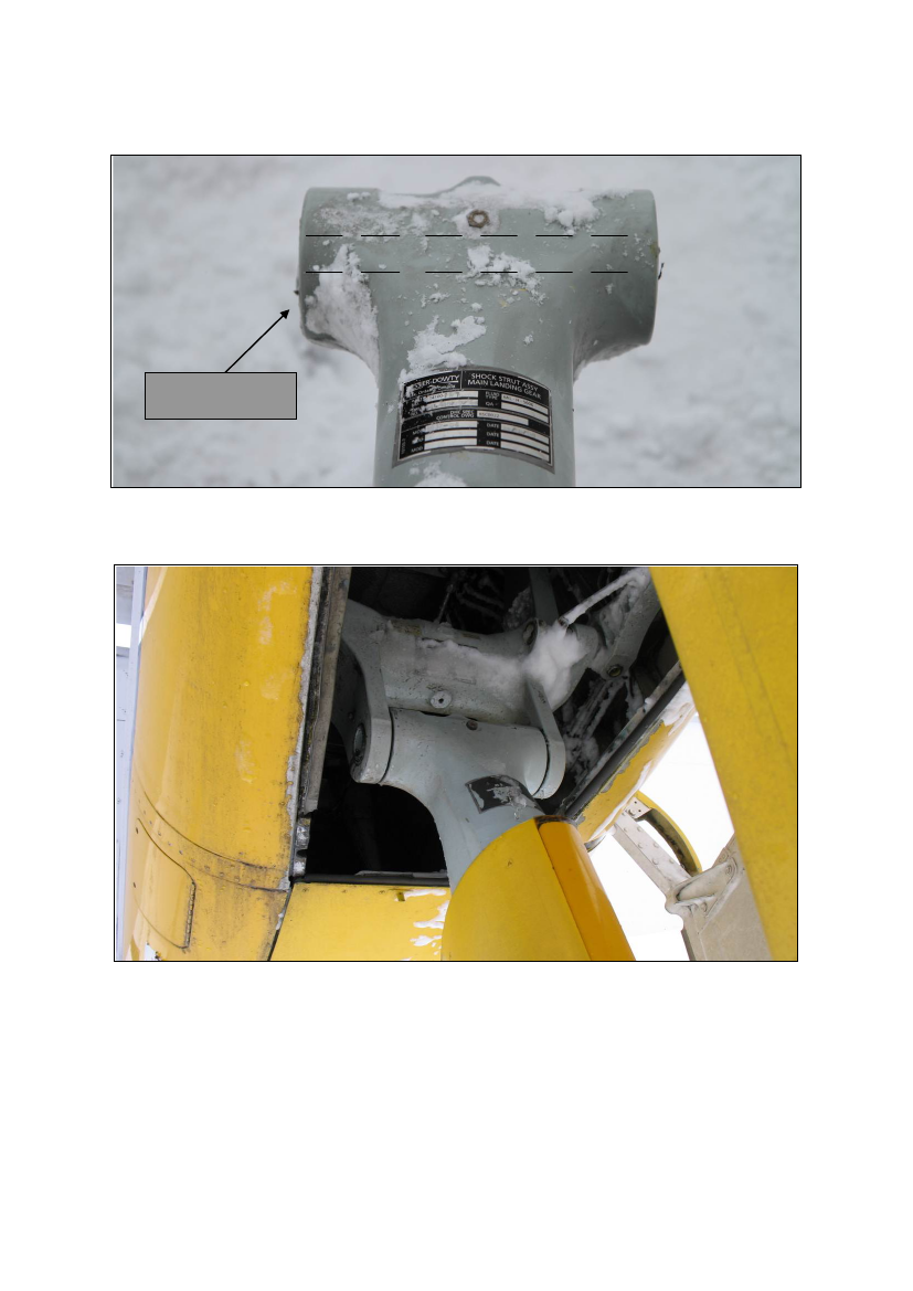
Shock strut MLH
The undamaged left main landing gear – see below.
Page 29
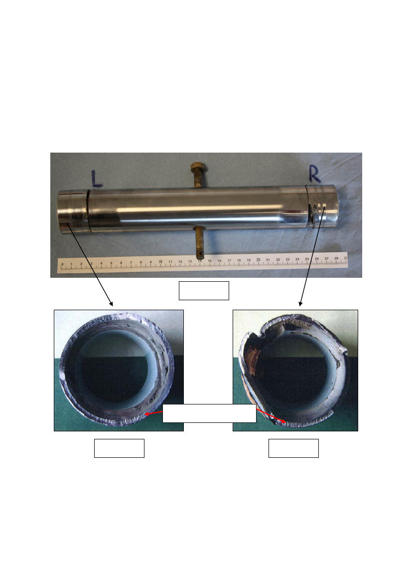
1.12.2 Fuse pin analysisThe mid-section of the fuse pin, (fig. 1 with the bolt) was found inside the head of shock strut to yoke.The head of the bolt indicates the forward direction (flight direction). The two ends (L & R) of the fuse pinwere found inside yoke junction to shock strut.A hint of inflection on the upper side of the fuse pin can be seen, fig 1. The remaining of the fracture in thenature of a clean shear - see figure 1, 2 and 3.
Fig. 1
Vertical upward marks.
Fig. 2
Fig. 3
Page 30
The fuse pin was sent to the laboratory for a metal analysis. The analysis revealed the following:The surface of the fractures from those pieces found in the gear yoke, showed marks coming fromvertical upward force. This force triggered the fracture. See fig. 2 and 3.To investigate whether there should be signs of material defects or pre-existing cracks in the fuse pin, thesurfaces of fractures were examined by a Scanning Electron Microscope (SEM).The investigation only found areas there were smeared, which did not give fractographic information andareas with dimples. Examples of areas that were found dimpled are shown in the fig. 4 (distinct sheardimples) and fig 5 (dimples characterize as overload breakage in wholesome materials).
Fig. 4
Fig. 5
Conclusions:Fractures in the fuse pin were caused by shear (shearing).It predominantly was a vertical-shear leading to the fractures.There was no evidence of fault or pre-existing cracks in the fuse pin.
Page 31
1.12.3
The touchdown
The aircraft final position
Paint from the lower fuselage
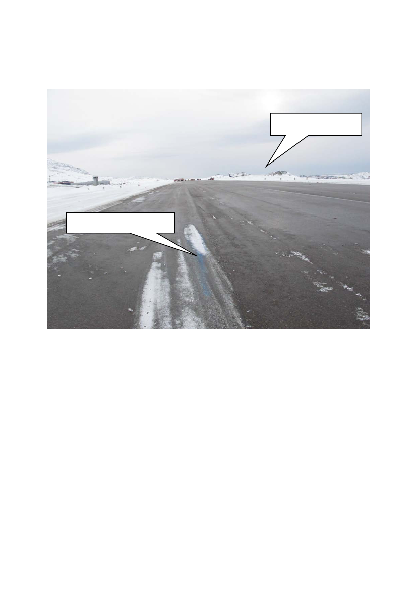
The aircraft touched down on runway 23 at time 16:09 hrs.At touchdown the right MLG fuse pin sheared; consequently the right MLG collapsed and the fuselagemade contact with the runway.The wideness marks from the aft fuselage was located approximately 200 meters (600 feet) passed thelanding threshold and approximately 10 meters (30 feet) to the left of the runway centerline.
Page 32
1.12.4
Vertical acceleration
FDR recorded data:FDR time in UTC1608:59.7501608:59.8751609:00.000Vertical acceleration0.755 G1.181 G3.894 G
The FDR recorded the vertical acceleration eight times each second.1.12.5Rate of descent
FDR recorded data:FDR time in UTC1608:57.8751608:58.8751608:59.875The FDR recorded the RA once each second.The last two recorded RA just prior to the accident were 14.7 feet and 1.2 feet above the ground.They indicated an average rate of descent of 13.5 feet/sec (810 feet per minute). But the actual rate ofdescent at touchdown might have been different.Radio Altimeter (RA) height24.4 feet14.7 feet1.2 feetRadio Altimeter rate of descent-9.7 feet/sec (582 fpm)13.5 feet/sec (810 fpm)
Page 33
1.12.6
Lateral acceleration
FDR recorded data:FDR time in UTC1608:59.5001608:59.7501609:00.000Lateral acceleration-0.162 G-0.891 G-1.541 G
The FDR recorded the lateral acceleration four times each second. The lateral acceleration at touchdownwas approximately -1.541 G.1.12.7Bank angle
FDR recorded data:FDR time in UTC1608:58.6251608:59.1251608:59.625Bank angle14.8� Right17.9� Right13.2� Right
The FDR recorded the bank angle twice each second. The bank angle just prior to touchdown wasapproximately 13.2� to the right.1.12.8Magnetic heading
FDR recorded data:FDR time in UTC1608:57.6251608:58.6251608:59.625Magnetic heading229.0�232.0�237.7�
The FDR recorded the magnetic heading once each second. The magnetic heading just prior to touchdownwas approximately 237.7�. The direction of runway 23 was 198.5� (GEO) or 228.5� (MAG).
Page 34
1.12.9
Pitch attitude
FDR recorded data:FDR time in UTC1608:58.8751608:59.3751608:59.875Pitch attitude-3.2�+0.5�+0.9�
The FDR recorded the pitch attitude twice each second. The pitch attitude just prior to touchdown wasapproximately +0.9� (0.9� nose up attitude).1.12.10 Calibrated airspeed (CAS)FDR recorded data:FDR time in UTC1608:57.6251608:58.6251608:59.625CAS110.0 knots93.5 knots85.0 knots
The FDR recorded the CAS once each second. The CAS just prior to touchdown was approximately 85knots. The Vref was 92 knots and the Vtgt was 107 knots.1.12.11 Engine torqueFDR recorded data:FDR time in UTC1608:57.5001608:58.0001608:58.5001608:59.0001608:59.5001609:00.000Left engine torque24.2%23.4%14.3%8.8%11.8%21.0%Right engine torque
Page 35
The FDR recorded the engine torque once each second for each engine. The engine torque at touchdownwas approximately 11.8% (left engine) and 21.0% (right engine).1.13NoneMedical and pathological information
1.14FireThere was no fire.1.15Survival aspectsThe accident was survivable.1.15.1Acceleration
FDR recorded data:EventLanding gear collapseNose gear collapseTime UTC16:09:00.00016:09:12.125Vertical G3.8941.293Longitudinal G-2.000-0.528Lateral G-1.541-0.022
The acceleration at time 16:09:00 occurred within one second and should not cause any injuries to personsproperly seated with their seatbelts fastened.The crew felt that the landing was a firm landing and not a hard landing and that the succeeding slidingdown the runway was like a sled ride.1.15.2 Cockpit and cabin structureDuring the landing sequence, the inside of the cockpit structure and the inside of the passenger cabinstructure remained almost intact.There were no loose objects injuring the passengers or the crew.1.15.3 Seats and seatbeltsThe passengers and the crew were using seatbelts. Neither seats nor seatbelts were overstressed or sufferedfrom malfunctioning.
Page 36
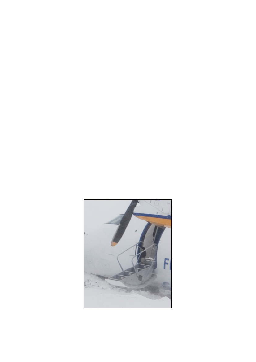
1.15.4 ExposureAt the time of the accident, the remaining jet fuel onboard was approximately 1 600 L. Most of the fuel waslocated in the wing fuel tanks. The wings remained intact except for the outer portion of the right wing.No significant amount of fuel (if any) left the fuel tank system during the accident.Neither passengers nor crew was exposed to jet fuel or any other substance.1.15.5 InjuriesNeither passengers nor crew were injured during the accident or during the evacuation [disembarkation].1.15.6 EvacuationAfter the aircraft came to a stop, the commander handled the on ground emergency from the cockpit and thefirst officer entered the passenger cabin to assist the cabin crew with the evacuation.The aircraft came to rest at a bank angle of 13.7� to the right and with a nose up attitude of 2.2�.The aircraft was equipped with one passenger door located at the left forward part of the passenger cabin,one service door located at the right forward part of the passenger cabin and two emergency exits located inthe middle of the passenger cabin below each wing.The passenger door had integrated footsteps on the inside of the door.
Page 37
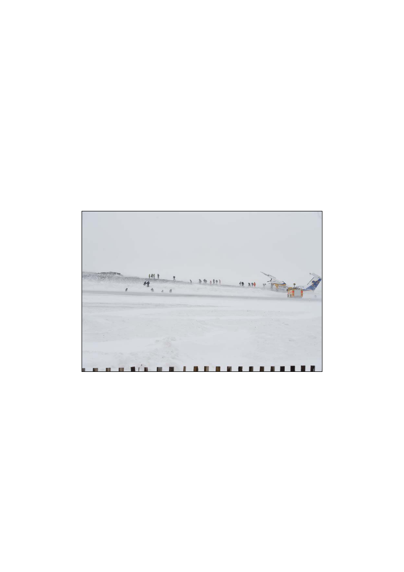
It became clear that there was no fire and there was no need to evacuate the aircraft in a hurry.Outside the aircraft, the temperature was around zero degrees centigrade and the wind velocity was 20 to 40knots. There was blowing and drifting snow.The forward left passenger door was not suitable to use as the bank angle of the aircraft made the integratedfootsteps useless since the last footstep was a half meter above the ground.The crew decided to disembark the passengers through the forward right service door.Before leaving the aircraft, the passengers took on their overcoats inside the cabin.Firefighters guided the passengers across the runway to the terminal building a few hundred meters away.
1.16None
Tests and research
1.17Organizational and management informationThe operator’s headquarters was located in Iceland.The area of operation was the North Atlantic area; primary Iceland, Faroe Islands and Greenland.The aircraft fleet consisted of twin-engine turboprop aircraft.Page 38
The operator had an approved Operations Manual system. The system contained a description of standardoperating procedures (SOP), information and limitations.Most of the destination aerodromes were located in mountain areas where the weather environment couldbe a challenging task.The majority of the airports had only non-precision approaches with a runway length of less than 2 000meters. Destination alternate aerodromes were typically located hundreds of miles away from thedestination airport.For that reason, diversions to the destination alternate aerodromes would be a challenging task operationallyand financially.1.18Additional information1.18.1 VMC approaches to runway 23ATS personnel operating at BGGH had observed similar ways of flying visual approaches as the visualapproach flown by TF-JMB. This way of flying the visual approach was occasionally used when the winddirection and the wind velocity would result in moderate to severe turbulence on final to runway 23.1.18.2 BGGH aerodrome and procedure briefingAn extract from the operator´s AOM – see appendix 31.18.3 Stabilized approach policyAn extract from the operator’s AOM – see appendix 4.1.19 Useful or effective investigation techniquesNone.2.Analysis2.1GeneralThe licenses and qualifications held by the flight crew, flight and duty times, the documented technicalstatus of the aircraft and the aircraft mass and balance had, in the AIB’s opinion, no influence on thesequence of events.2.2Flight planning and enrouteThe flight crew planned the flight from BGKK to BGGH with the destination alternate aerodrome BGSF.With reference to the operator’s instrument approach chart (LLZ DME approach to runway 23) and theBGGH aerodrome and procedure briefing, the latest TAF (at 13:00 hrs) before departure from BGKK at
Page 39
14:13/14:17 hrs, indicated marginal weather conditions (strong winds, a low visibility and a low cloudbase) for a successful approach and landing at BGGH.From a preplanning point of view, the forecasted weather conditions (0400 +sn blsn vv002) at the expectedapproach time at BGGH were below preplanning minima which would require preplanning with use of twodestinations alternate aerodromes instead of only one.The actual weather conditions at BGGH and enroute weather briefings were equivalent to the forecastedweather conditions.2.3Approach to BGGHWith reference to the operator’s aerodrome and procedure briefing and the latest reported wind conditionsfrom Nuuk AFIS before landing (wind direction 180� (magnetic), wind speed 17 knots maximum 42 knotsand wind direction variable between 140� (magnetic) and 220� (magnetic)), a landing was prohibited.Throughout the approach, a combination of strong winds and moderate to severe orographic turbulencefrom the surrounding mountainous terrain increased the flight crew load.Though operating within the general crosswind limitations of the aircraft, the flight crew had difficulties ofmaintaining stabilized approach parameters. Furthermore, the flight crew at low altitude changed a briefedand prepared decision on the use of landing flap setting.At altitudes below 500 feet above ground level, the extent of turbulence and flight crew work loadincreased. The flight crew most likely suffered from task saturation and information overload. No flightcrew call outs on divergence from the operator’s stabilized approach policy were made.Important low altitude stabilized approach parameters like airspeed, bank angle and runway alignment werenot sufficiently corrected. An optimum crew resource management was not present.The AIB believes that the flight crew was solely focused on landing and that task saturation mentallyblocked a decision of going around.Just before the landing phase, the aircraft was not appropriately stabilized in order to make a safe landing.2.4 LandingCompensating the aircraft in the flare not being appropriately stabilized (low airspeed and banking), theflight crew did abrupt maneuvers leading to a sideways movement hard landing.An excess load of the right MLG at touchdown caused the fuse pin to shear as a result of overload andconsequently, the right MLG collapsed.
Page 40
3.3.1
ConclusionsFindings- The licenses and qualifications held by the flight crew, flight and duty times, the documentedtechnical status of the aircraft and the aircraft mass and balance had no influence on the sequenceof events- The flight crew planned the flight from BGKK to BGGH with the destination alternate BGSF- The latest BGGH TAF before departure from BGKK indicated marginal weather conditions(strong winds, low visibility and low cloud base) for a successful approach and landing at BGGH- The forecasted weather conditions at the expected approach time at BGGH were belowpreplanning minima (use of two destination alternate aerodromes)- The actual weather conditions at BGGH and enroute weather briefings were equivalent to theforecasted weather conditions- With reference to the operator’s aerodrome and procedure briefing and the latest reported windconditions from Nuuk AFIS before landing, a landing was prohibited- Strong winds and moderate to severe orographic turbulence from the surrounding mountainousterrain increased the flight crew load- On approach, the flight crew had difficulties of maintaining stabilized approach parameters- The flight crew most likely suffered from task saturation and information overload- No flight crew call outs on divergence from the operator’s stabilized approach policy were made- An optimum crew resource management was not present- Important low altitude stabilized approach parameters like airspeed, bank angle and runwayalignment were not sufficiently corrected- The flight crew was solely focused on landing and task saturation mentally blocked a decision ofgoing around- A divergence from the operator’s stabilized approach policy caused an unstabilized approach anda hard landing leading to an excess load of the right MLG at touchdown- The right MLG fuse pin sheared as a result of overloead
3.2
Factors- A divergence from the operator’s stabilized approach policy caused an unstabilized approach anda hard landing leading to an excess load of the right MLG at touchdown- The right MLG fuse pin sheared as a result of stress
Page 41
3.3SummaryAdverse wind and turbulence conditions at BGGH led to flight crew task saturation on final approach and abreakdown of optimum cockpit resource management (CRM) resulting in a divergence from the operator’sstabilized approach policy.The divergence from the operator’s stabilized approach policy caused an unstabilized approach and a hardlanding leading to an excess load of the right MLG at touchdown.According to its design, the right MLG fuse pin sheared as a result of stress.4.Safety recommendations4.1Safety recommendationThe investigation has not resulted in any recommendations being made.4.2Preventive actionsThe operator implemented following initiatives:Operational initiatives- All commanders were immediately contacted by the chief pilot in order to emphasize that theSOP should be followed in BGGH as well as elsewhere- Discussion on the stabilized approach policy- During recurrent training, above items were emphasized- Simulator training for all crew included a similar scenario like this accident.- Stricter wind limits for BGGH were introduced and a graphical wind-rose was published- During emergency training, special focus and discussions on importance of immediate actionby the crew following an accident/incident.Maintenance initiativesThe operator implemented the following as a precautionary measure for the second aircraft in operation:- Shear pin inspection in accordance with the Bombardier AMM – rotation and freedom ofmovement- Replacement of both shear pinsWhen the Q100 was replaced with the Q200 aircraft the following was scheduled:- Replacement of both shear pins where scheduled at next C check
Page 42
- Amended the approved AMP with further inspection to be accomplished at each C check inaccordance with the Bombardier AMM- Flight data monitoring under development to monitor G loads during landing5.1.2.3.4.AppendicesApproach and landingFDR plotsBGGH aerodrome and procedure briefingStabilized approach policy
Page 43
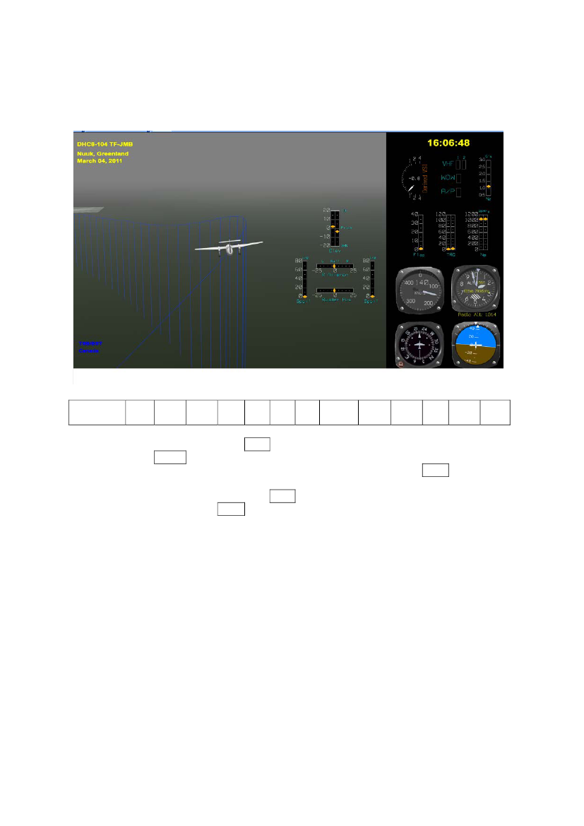
Appendix 1 – approach and landingTime 16:06:48 – approximately 1 912 feet RA – flaps 15� selected
UTC16:06:48,37516:06:48,50016:06:48,62516:06:48,75016:06:48,87516:06:49,00016:06:49,12516:06:49,25016:06:49,375
P.A.feet1914
CASknots
Pitch Att1,1
RollAtt
Eng 1TQ %
Eng 2TQ %
M.H.Deg
VerticalAccel (g's)1,023
Prop 1RPM
Prop 2RPM
Flap(Deg)
PitchTrim(Deg)
RadioAlt(feet)
3,5140,5-5,6222,9
0,9820,9591,016
1053,5
1,7
-2,11910,4
0,86-5,6
0,9911,031,061,0711056,4
1902
1,1
1,082
The flaps were selected while the aircraft was in a left turn banking 5.6� (-5.6). The flaps were movingthrough 1.7� towards 15�.The recommended airspeed with flaps up was 148 knots and the actual CAS was 140.5 knots.The engine torque was approximately “in idle” while the flaps were moving.
Page 44
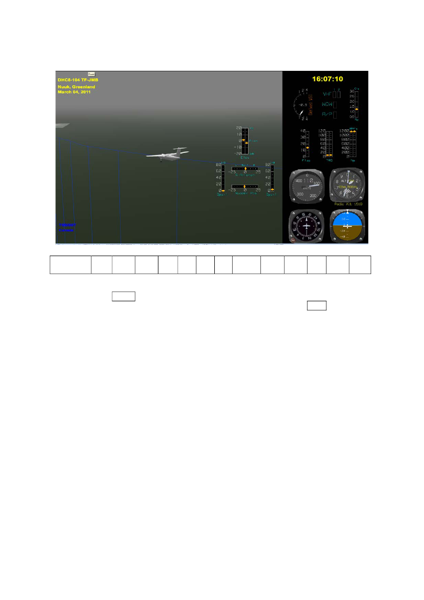
Time 16:07:10 – approximately 1 517 feet RA – flaps 15� set
UTC16:07:10,37516:07:10,50016:07:10,62516:07:10,75016:07:10,87516:07:11,00016:07:11,12516:07:11,25016:07:11,375
P.A.feet1496
CASknots
Pitch Att-3,3
RollAtt
Eng 1TQ %
Eng 2TQ %
M.H.Deg
VerticalAccel (g's)1,048
Prop 1RPM
Prop 2RPM
Flap(Deg)
PitchTrim(Deg)
RadioAlt(feet)
8,8110-0,5194,4
1,0571,1081,195
1187,5
14,7
-2,11514,9
-2,990,2
1,1121,0941,1191,0481192,3
1482
-3,3
1,027
The flaps were set at 15� (14.7).The Vtgt was Vref flaps 15 (102 knots) plus correction for wind (15 knots) equal to 117 knots and theactual CAS was 110 knots.The propeller RPM were increased from approximately 1 050 rpm to approximately 1 200 rpm.The engine torque was approximately “in idle”.
Page 45
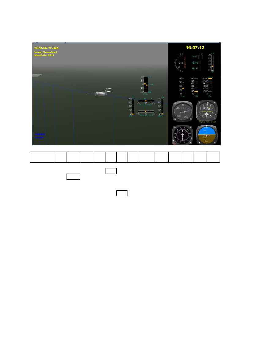
Time 16:07:12 – approximately 1 485 feet RA – before landing checklist completed
UTC16:07:12,37516:07:12,50016:07:12,62516:07:12,75016:07:12,87516:07:13,00016:07:13,12516:07:13,25016:07:13,375
P.A.feet1468
CASknots
Pitch Att-4
RollAtt
Eng 1TQ %
Eng 2TQ %
M.H.Deg
VerticalAccel (g's)0,984
Prop 1RPM
Prop 2RPM
Flap(Deg)
PitchTrim(Deg)
RadioAlt(feet)
16,61130,5194,2
0,9840,9840,991
1204
14,7
-2,11485,6
-4,1200
1,0020,9980,9981,0161204,4
1454
-4
1,016
The “before landing checklist” was completed.At this time, the landing flap setting was 15�.The Vtgt was 117 knots and the actual CAS was 113 knots.The engine torque was increased to approximately 20%.
Page 46
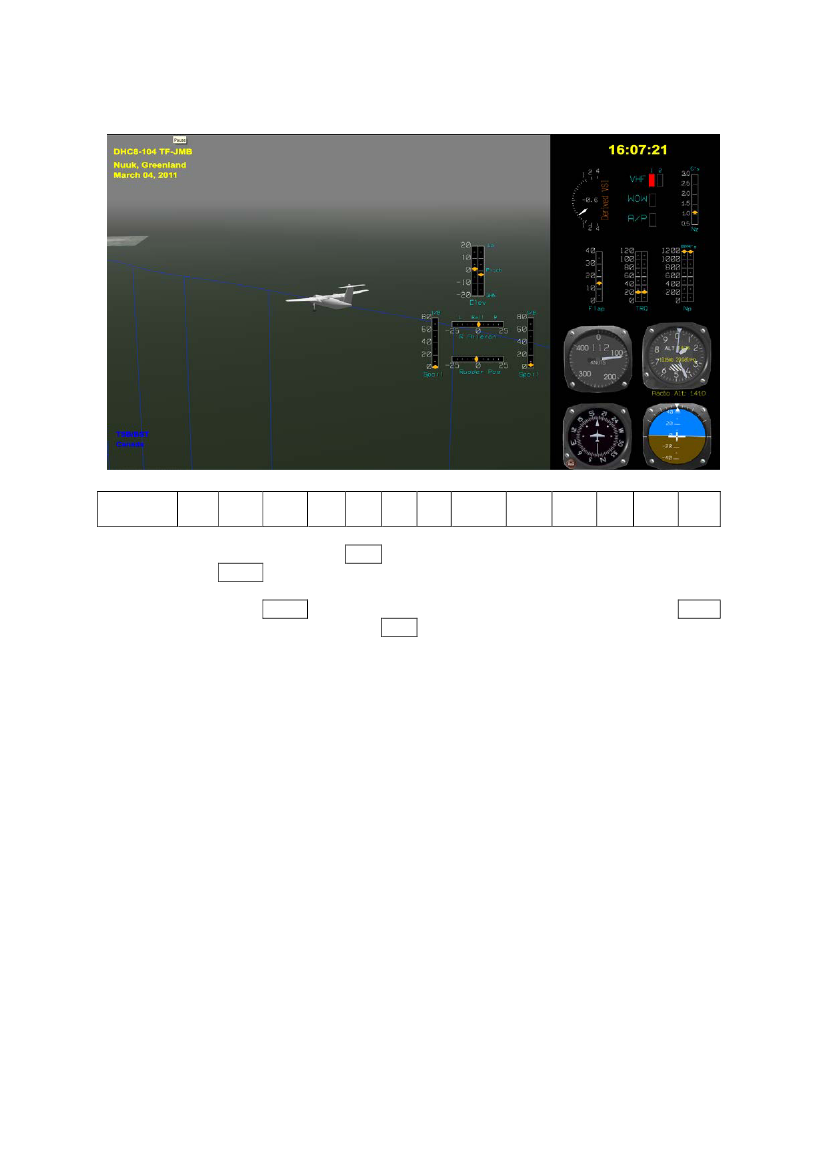
Time 16:07:21 – 1 408 feet RA – 3 nm out
UTC16:07:21,37516:07:21,50016:07:21,62516:07:21,75016:07:21,87516:07:22,00016:07:22,12516:07:22,25016:07:22,375
P.A.feet1382
CASknots
Pitch Att-1,1
RollAtt
Eng 1TQ %
Eng 2TQ %
M.H.Deg
VerticalAccel (g's)0,979
Prop 1RPM
Prop 2RPM
Flap(Deg)
PitchTrim(Deg)
RadioAlt(feet)
22,9112-1,8193,5
0,9020,8950,95
1203,3
-2,11407,51195,6
-0,923-3,7
0,9790,951,0091,046
1374
-0,6
1,048
The Pitch Attitude increased from approximately -3� to -1� (nose down).The Vtgt was 117 knots and the actual CAS was 112 knots.The engine torque was increased to approximately 23%.
Page 47
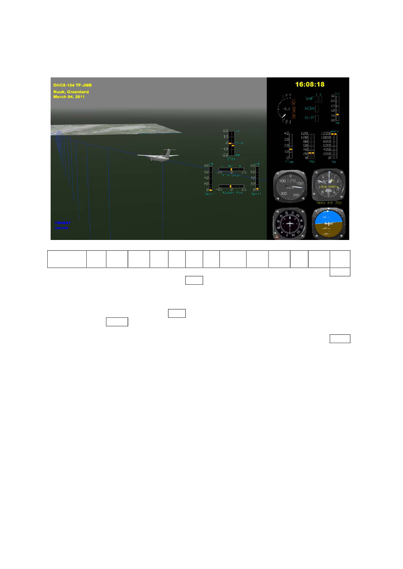
Time 16:08:18 – approximately 784 feet RA
UTC16:08:18,87516:08:19,00016:08:19,12516:08:19,25016:08:19,37516:08:19,50016:08:19,62516:08:19,75016:08:19,875
P.A.feet
CASknots
Pitch Att-2,9
RollAtt
Eng 1TQ %
Eng 2TQ %
M.H.Deg
VerticalAccel (g's)1,13
Prop 1RPM
Prop 2RPM
Flap(Deg)
PitchTrim(Deg)
RadioAlt(feet)787,4
265,4
1,2041,2471,275
1193,8
732
-2,125,71222,5197,6
1,1991,2061,2681,211-1,2776,41197,8
-3,1
0,991
The aircraft continued on a track at an offset angle towards the landing threshold runway 23 at an angle of25� to 35�.The Pitch Attitude was approximately -3� to -2� (nose down).The Vtgt was 117 knots and the actual CAS was 122 knots.The engine torque was increased to approximately 26%.
Page 48
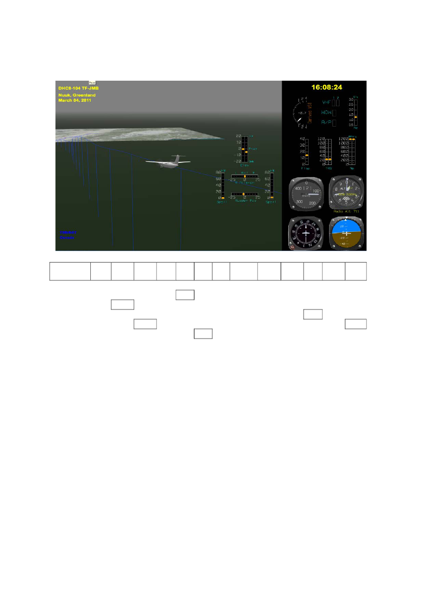
Time 16:08:24 – approximately 711 feet RA - flaps 35� selected
UTC16:08:24,37516:08:24,50016:08:24,62516:08:24,75016:08:24,87516:08:25,00016:08:25,12516:08:25,25016:08:25,375
P.A.feet650
CASknots
Pitch Att-4
RollAtt
Eng 1TQ %
Eng 2TQ %
M.H.Deg
VerticalAccel (g's)1,078
Prop 1RPM
Prop 2RPM
Flap(Deg)
PitchTrim(Deg)
RadioAlt(feet)
25,9121,54200,4
0,9611,0021,185
1205,9
15,1
-1,2709,2
-5265,8
1,130,8810,6790,5381201,1
682
-5,7
0,615
The flaps were moving from flap setting 15� towards flap setting 35�.The aircraft continued on a track at an offset angle towards the landing threshold runway 23 at an angle of25� to 35�. The Pitch Attitude decreased to approximately -4� to -6� (nose down).The Vtgt was 117 knots and the actual CAS was 121.5 knots.The engine torque was steady at approximately 26%.
Page 49
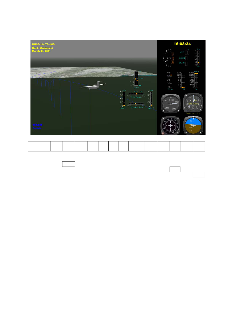
Time 16:08:34 – approximately 626 feet RA – flaps 35� set
UTC16:08:34,37516:08:34,50016:08:34,62516:08:34,75016:08:34,87516:08:35,00016:08:35,12516:08:35,25016:08:35,375
P.A.feet578
CASknots
Pitch Att-7,3
RollAtt
Eng 1TQ %
Eng 2TQ %
M.H.Deg
VerticalAccel (g's)0,744
Prop 1RPM
Prop 2RPM
Flap(Deg)
PitchTrim(Deg)
RadioAlt(feet)
0115,5-4200,9
0,7340,7370,792
1139,9
34,1
-0,2625
-6,61-0,7
0,8720,9060,9520,9241139,2
548
-5,5
0,874
The flaps were set at flap setting 35�.The aircraft continued on a track towards the landing threshold runway 23 at an angle of 25� to 35�.During the flaps extension from flap setting 15� to flap setting 35�, the engine torque decreased fromapproximately 26% to 0% (idle power). The pitch attitude decreased to approximately -5� to -7� (nosedown).
Page 50
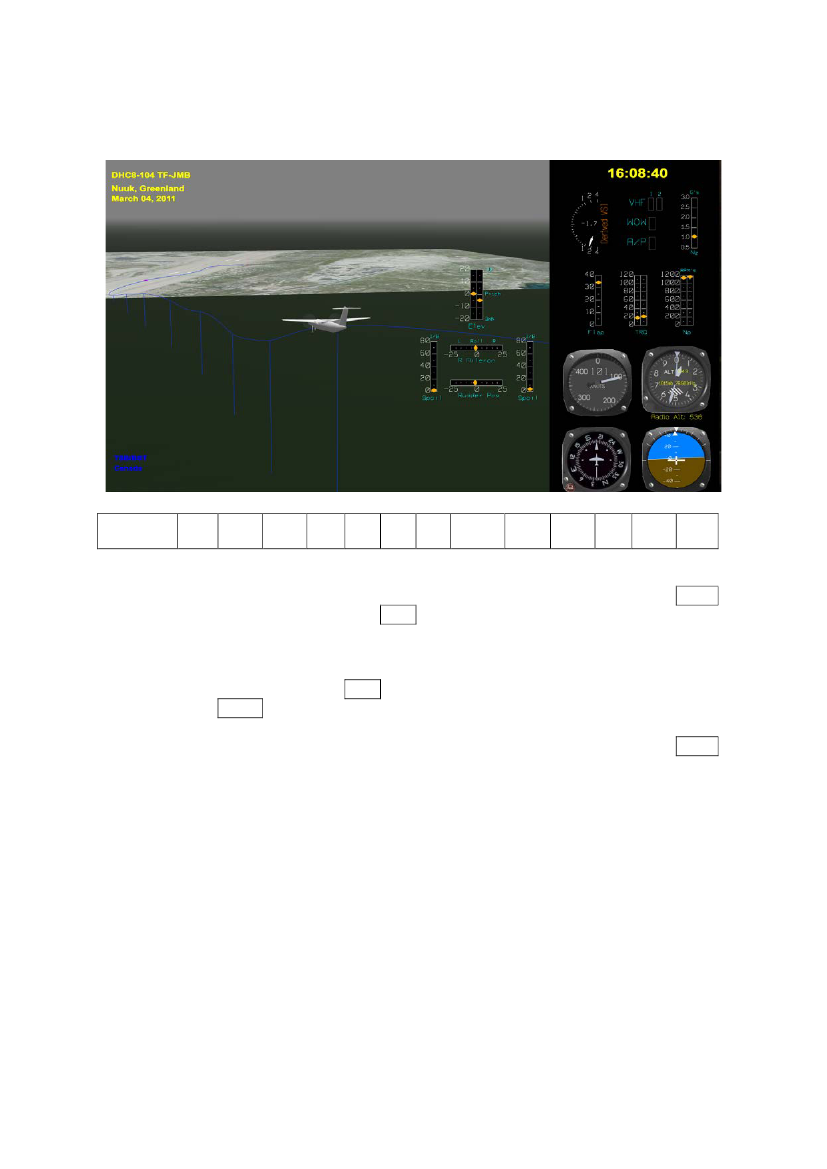
Time 16:08:40 – approximately 530 feet RA – airspeed 17 knots below Vtgt
UTC16:08:40,62516:08:40,75016:08:40,87516:08:41,00016:08:41,12516:08:41,25016:08:41,37516:08:41,50016:08:41,62516:08:41,75016:08:41,875
P.A.feet
CASknots101
Pitch Att
RollAtt2,5
Eng 1TQ %
Eng 2TQ %
M.H.Deg200,7
VerticalAccel (g's)0,8560,947
Prop 1RPM
Prop 2RPM
Flap(Deg)
PitchTrim(Deg)
RadioAlt(feet)
34,2
-0,2529,8
-2,5292,6
0,9731,0021,1261,0761150,2
458
-1,840,3904,6201,1
1,0181,0921,1191-0,2468,81125,6
-1,6
1,016
The aircraft continued on a track towards the landing threshold runway 23 at an angle of 25� to 35�.As the airspeed momentarily decreased to 90 knots, the engine torque increased from slightly above idleto 30% - 40%.The Vtgt was 107 knots, and the actual CAS momentarily decreased to 90 knots.
Page 51
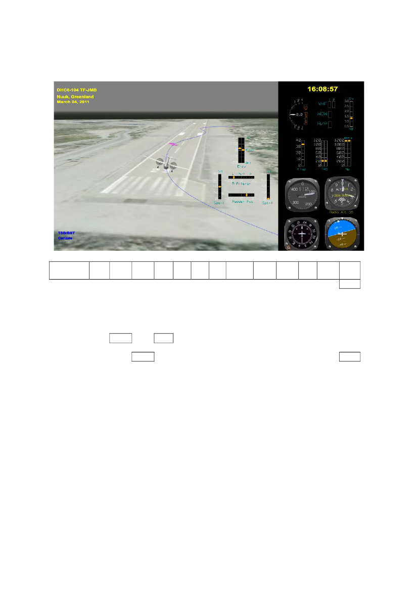
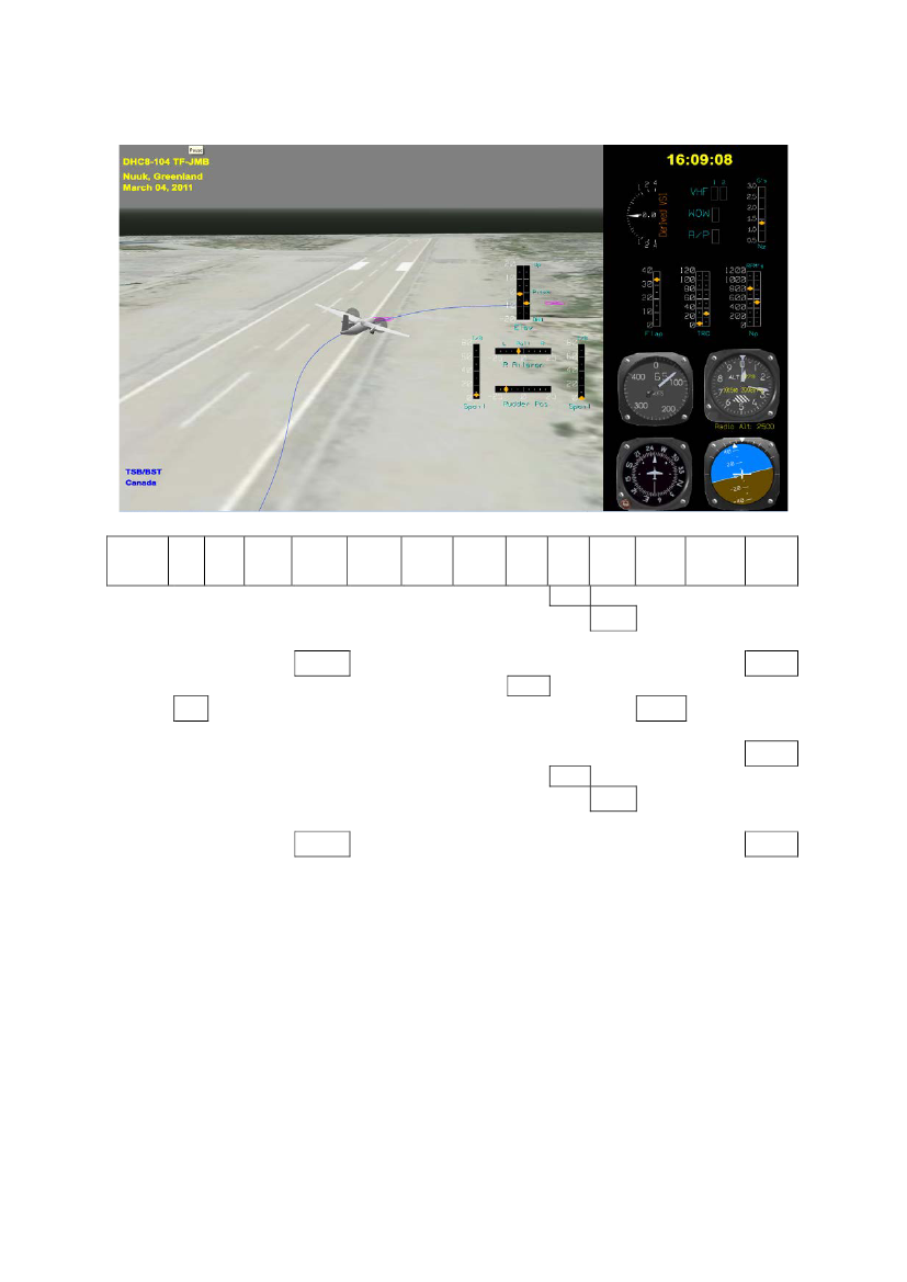
Time 16:08:57 – 30 feet above the runway – banking 18� to the right
UTC16:08:56,87516:08:57,00016:08:57,12516:08:57,25016:08:57,37516:08:57,50016:08:57,62516:08:57,75016:08:57,875
P.A.feet
CASknots
Pitch Att-4,8
RollAtt
Eng 1TQ %
Eng 2TQ %
M.H.Deg
VerticalAccel (g's)1,208
Prop 1RPM
Prop 2RPM
Flap(Deg)
PitchTrim(Deg)
RadioAlt(feet)37,8
2416
1,1471,2561,256
1193
240
-4,624,211018,3229
1,1491,2241,111,053-0,324,41186,8
-5,8
1,027
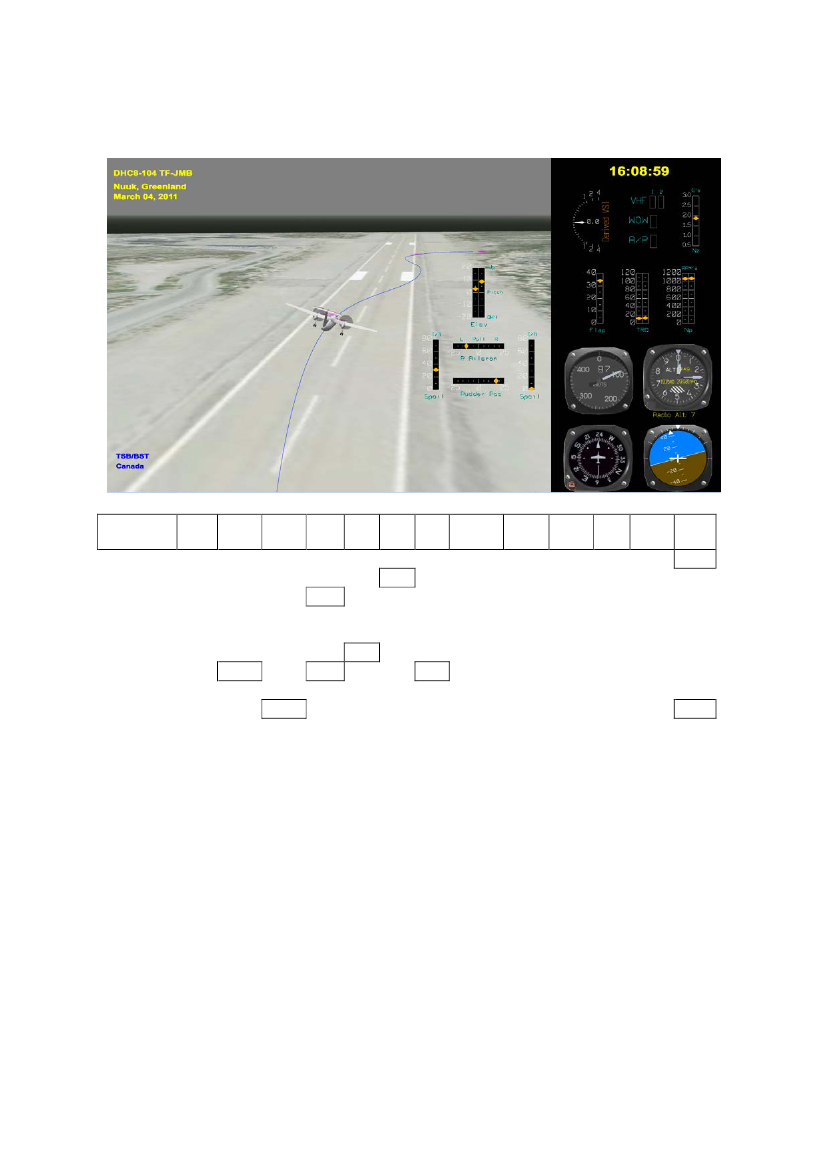
The aircraft had passed the runway threshold and descended through 30 feet above runway 23.The aircraft was banking up to 18.3� to the right but it was drifting to the left. The aircraft overshot therunway centerline to the left. The engine torque was around 24% and was about to be reduced. The RAdecreased from 37.8 feet to 24.4 feet or 13.4 feet in one second (804 fpm).The pitch attitude decreased from the previous -3� to -4� (nose down) to -5.8� (nose down).
Page 52
The picture was taken near the road to the left of runway 23 while the aircraft approached the landingthreshold.
Page 53
Time 16:08:59 – the flare
UTC16:08:58,87516:08:59,00016:08:59,12516:08:59,25016:08:59,37516:08:59,50016:08:59,62516:08:59,75016:08:59,875
P.A.feet
CASknots
Pitch Att-3,2
RollAtt
Eng 1TQ %
Eng 2TQ %
M.H.Deg
VerticalAccel (g's)1,021
Prop 1RPM
Prop 2RPM
Flap(Deg)
PitchTrim(Deg)
RadioAlt(feet)14,7
917,9
0,9930,9310,863
1142,1
194
0,511,88513,2237,7
1,7621,3940,5330,755-0,21,21055,3
0,9
1,181
The aircraft was in the landing flare. The aircraft was still banking up to 17.9� to the right and the drift tothe left had stopped. The aircraft was left of the runway centerline.The engine torque was reduced to around 10%. The RA had dropped from 14.7 feet to 1.2 feet or 13.5 feetin one second (810 fpm). The pitch attitude was increased from the previous -5.8� (nose down) to +0.9�(nose up) in two seconds.The target airspeed was 107 knots (Vref+15). The CAS was 85 knots.The aircraft magnetic heading (MH) was 237.7� while the runway magnetic heading was 228.5�.
Page 54
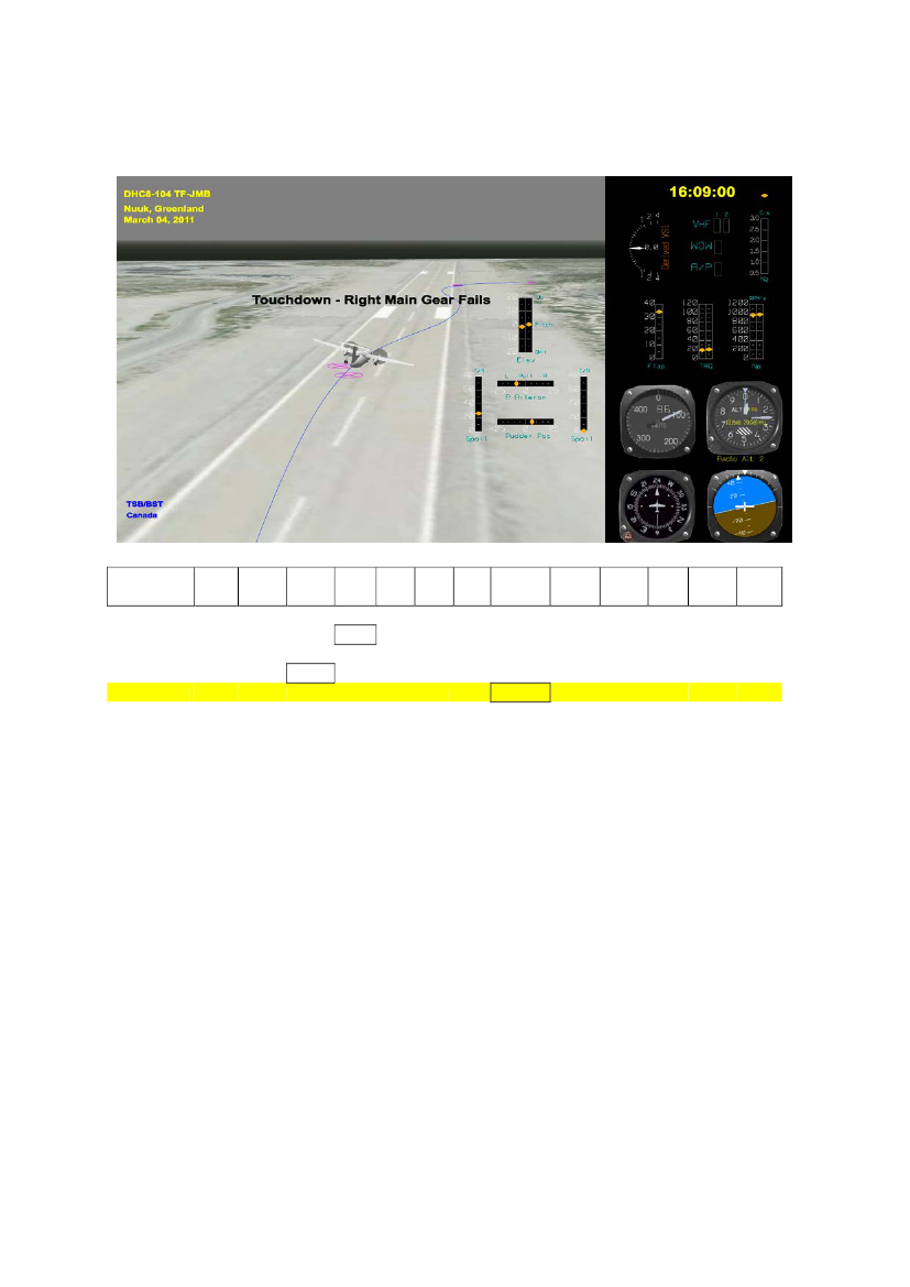
Time 16:09:00 – touchdown
UTC16:08:59,50016:08:59,62516:08:59,75016:08:59,87516:09:00,00016:09:00,12516:09:00,25016:09:00,375
P.A.feet
CASknots
Pitch Att
RollAtt
Eng 1TQ %11,8
Eng 2TQ %
M.H.Deg
VerticalAccel (g's)1,394
Prop 1RPM1055,3
Prop 2RPM
Flap(Deg)
PitchTrim(Deg)
RadioAlt(feet)
85
13,2
237,7
0,5330,755-0,21,2953,1
0,92111,4
1,1813,8940,9080,929
188
1,4
0,588
The RA had dropped from 14.7 feet to 1.2 feet in one second. The average rate of descent from RA14.7 feet to RA 1.2 feet was 13.5 fps (810 fpm).The aircraft touched down on runway 23 approximately 10 meters (30 feet) left of the runwaycenterline and approximately 200 meters (600 feet) from the runway landing threshold.Just prior to touchdown the aircraft was banking 13.2� to the right with a pitch attitude of +0.9� (noseup). As a consequence, the touchdown was on the right MLG only. The magnetic heading attouchdown was approximately 237.7�.The right MLG fuse pin sheared and consequently, the right MLG collapsed.
Page 55
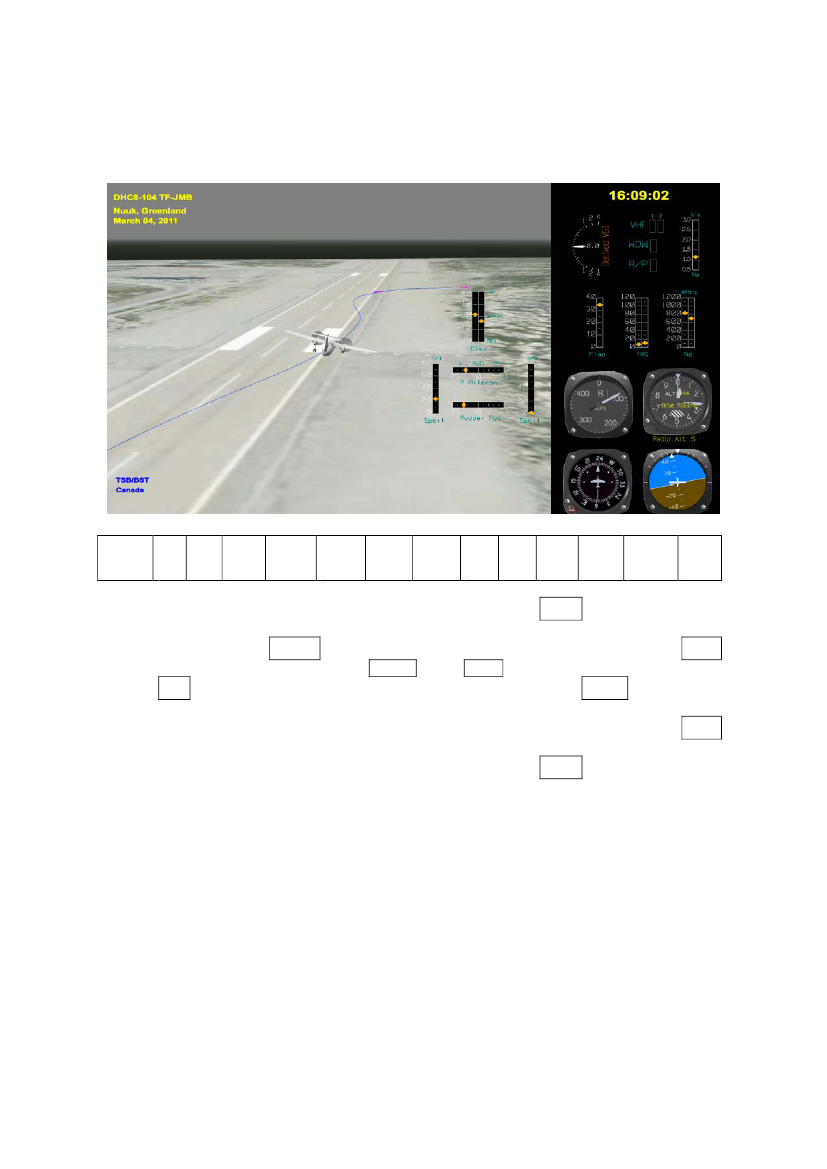
Time 16:09:02 – aircraft sliding down the runway
UTC
CAS
MH
VerticalAccel(g's)1,0851,0270,9931,0731,071
Prop BetaEng#1
Prop BetaEng#2
Prop 1RPM(rpm)
Prop 2RPM(rpm)611,7
Eng 1Torque(%)
Eng 2Torque(%)13,3
Eng 1NH(%rpm)
Eng 2NH(%rpm)
RollAttitude
RudderPositon
16:09:02,00016:09:02,12516:09:02,25016:09:02,37516:09:02,50016:09:02,62516:09:02,75016:09:02,87516:09:03,00016:09:03,12582,5237,3
77,3
12,1
Not Beta
Not Beta820,57,976,912
-14,3
1,0550,921,0111,0760,961748,71073,5
-14
12,5
The aircraft was sliding down runway 23.The directional control of the aircraft was achieved by the use of the rudder.The CAS was 82.5 knots making the rudder effective.Both the engine turbines were running. The propeller on engine #1 was producing forward power(7.9% torque)] and was not used to maintain directional control.
Page 56
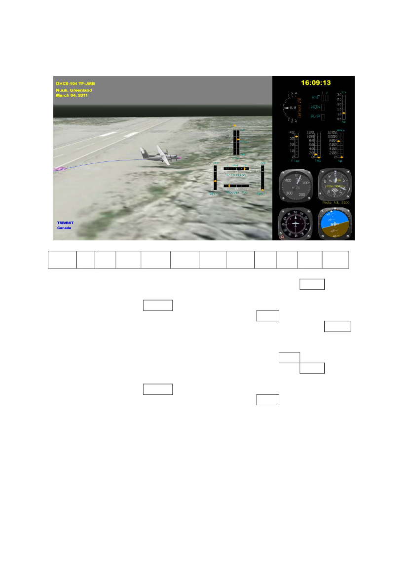
Time 16:09:08 – aircraft sliding off the runway
UTC
CAS
MH
VerticalAccel(g's)0,7991,3850,9840,9181,277
Prop BetaEng#1
Prop BetaEng#2
Prop 1RPM(rpm)
Prop 2RPM(rpm)655,7
Eng 1Torque(%)
Eng 2Torque(%)28,8
Eng 1NH(%rpm)
Eng 2NH(%rpm)
RollAttitude
RudderPositon
16:09:08,00016:09:08,12516:09:08,25016:09:08,37516:09:08,50016:09:08,62516:09:08,75016:09:08,87516:09:09,00016:09:09,12516:09:09,25016:09:09,37564,5252,2
72,2
14,1
Not Beta
Not Beta827,86,368,414,8
-15,1
1,1011,0461,111,1851,1581,030,927Not BetaNot Beta331,126,673,5
-15,1
13,4
-15,2
The aircraft slid off runway 23 and departed the runway to the right.The directional control of the aircraft was controlled by the use of the rudder. The rudder was in a fullleft deflection (-15). The CAS had dropped to 64.5 knots making the rudder less effective.Both the engine turbines were running. The propeller on engine #1 was still producing forward power(6.3% torque)]. The propeller on engine #2 appeared to produce forward power (28.8% to 26.6%torque) but the outer parts of the propeller blades were gone.
Page 57
Time 16:09:13 – the aircraft came to rest
UTC16:09:13,00016:09:13,12516:09:13,25016:09:13,37516:09:13,50016:09:13,62516:09:13,75016:09:13,87516:09:14,00016:09:14,12516:09:14,25016:09:14,37516:09:14,500
CAS
MH
VerticalAccel (g's)0,9540,9750,9630,9310,947
Prop BetaEng#1
Prop BetaEng#2
Prop 1RPM (rpm)
Prop 2RPM (rpm)33,7
Eng 1Torque(%)
Eng 2Torque(%)0,1
Eng 1 NH(%rpm)
Eng 2 NH(%rpm)
74,7
Not Beta
Not Beta797,415,630,2
31,5
301,3
0,9730,9470,9380,9310,9540,9540,9910,982Not BetaNot Beta789,7158,40,374,6
The aircraft came to rest to the right of runway 23.Both the engine turbines were still running. The propeller on engine #1 had increased the forwardpower to around 15.0% torque. The propeller on engine #2 did not to produce any forward power(0.3% torque).The aircraft pitch angle was +2� nose up and the bank angle was 13� right wing down.Page 58
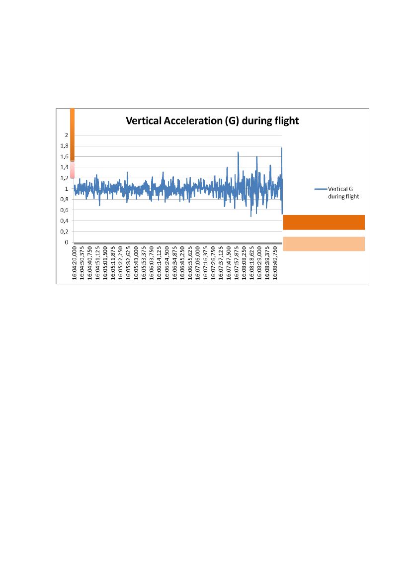
Vertical acceleration during flight
Severe turbulenceModerate turbulence
Page 59
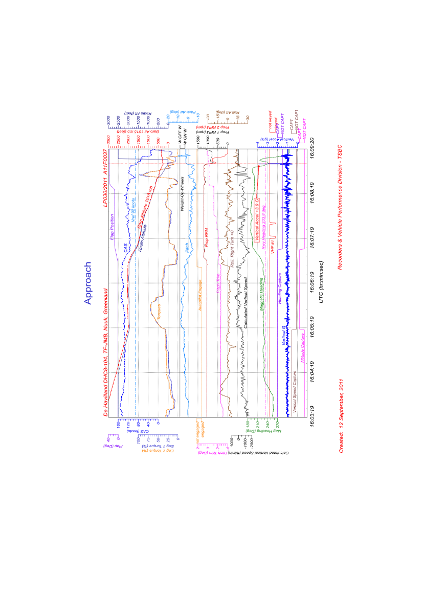
Appendix 2 – FDR plotsThe approach
Page 60
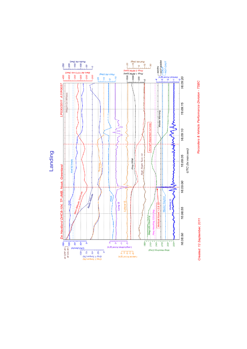
The landing
Page 61
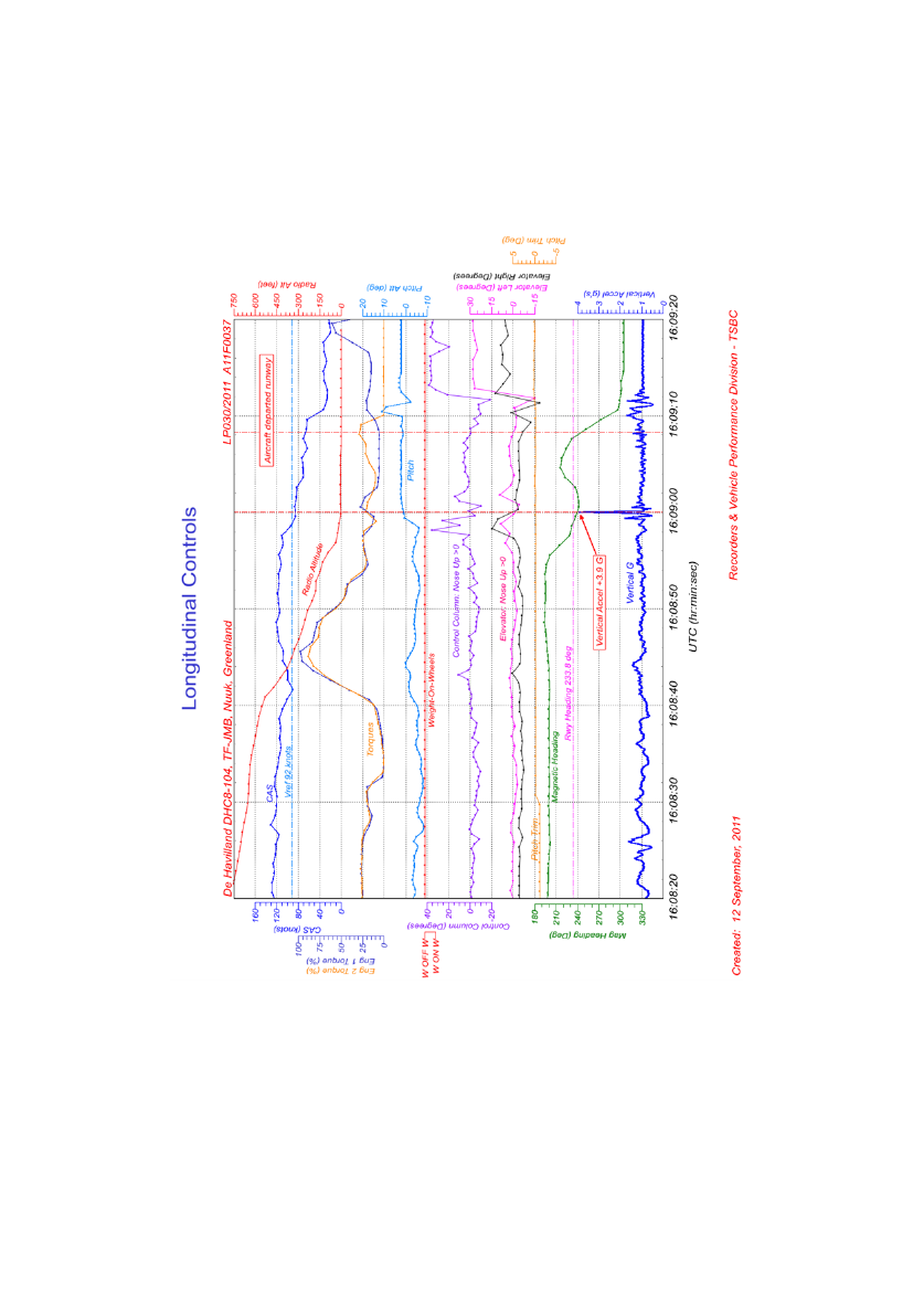
Longitudinal controls
Page 62
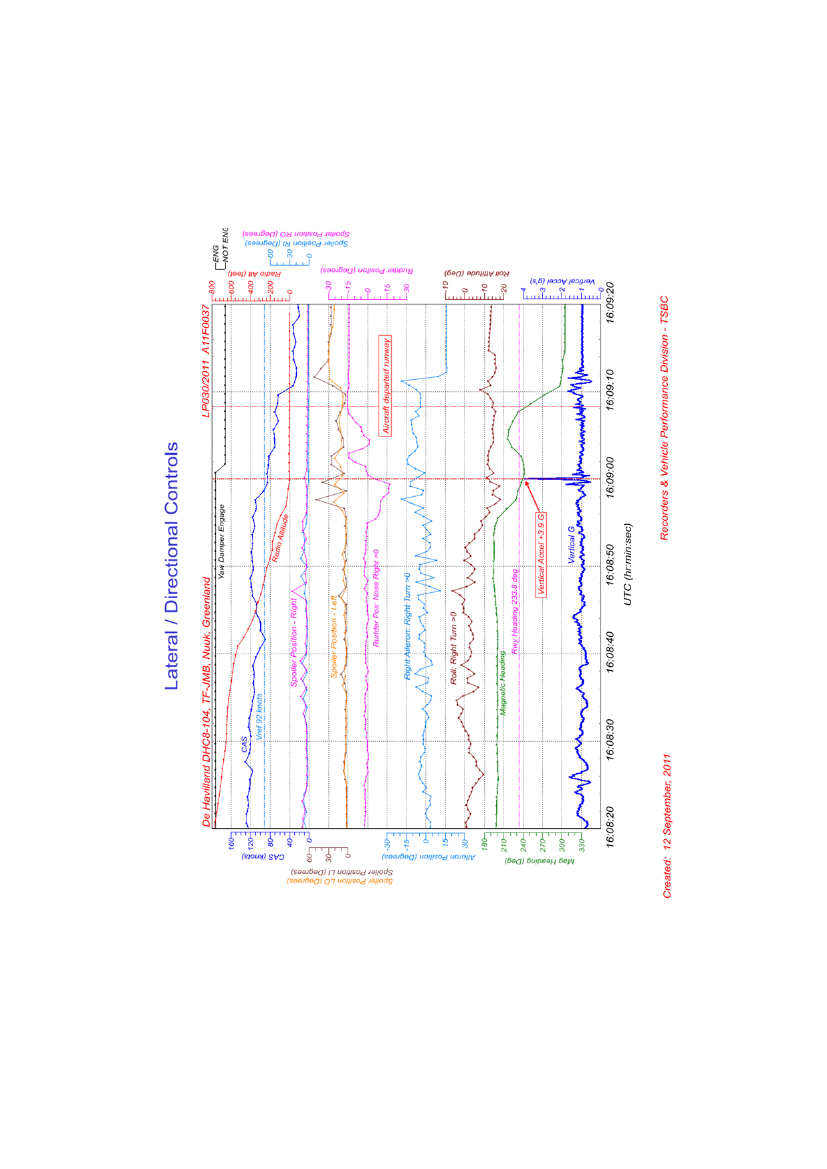
Lateral and directional controls
Page 63
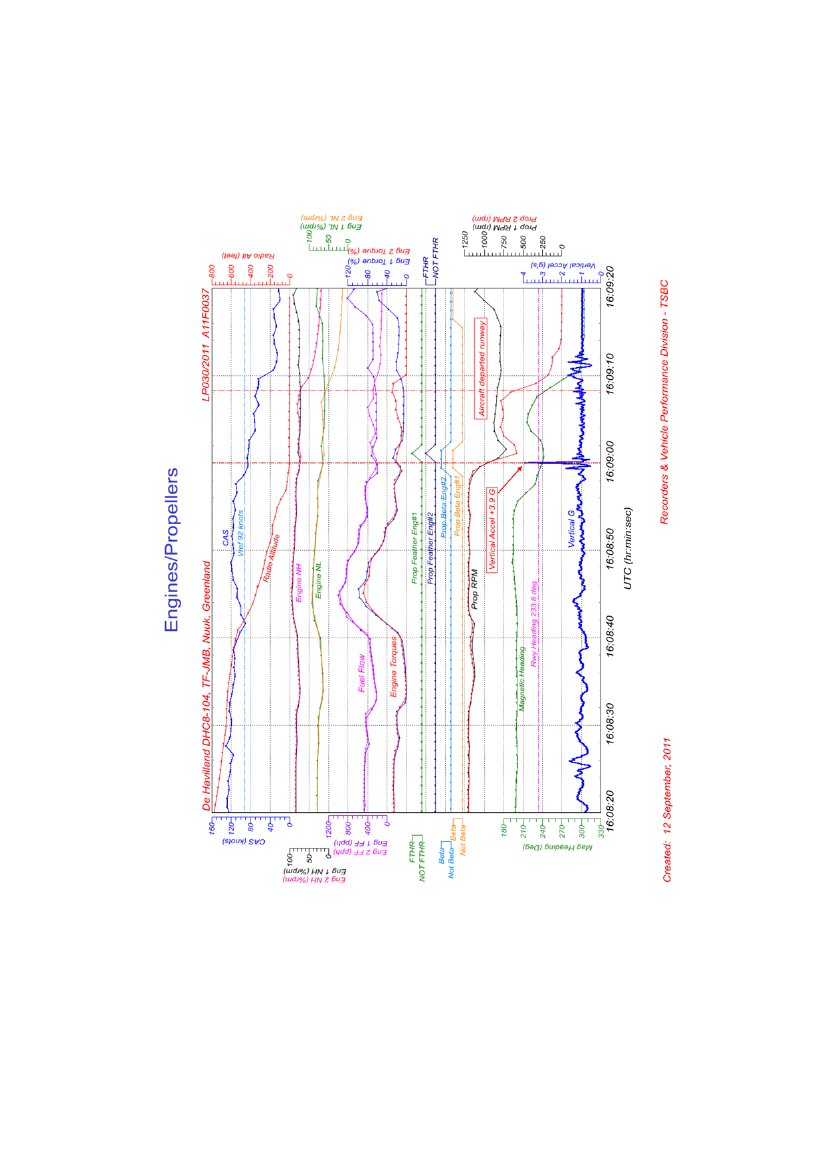
Engines and propellers
Page 64
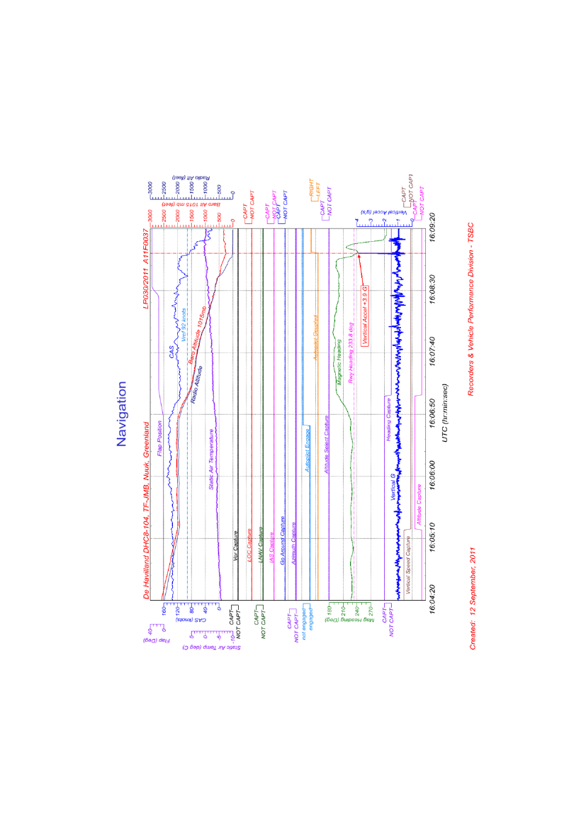
Navigation
Page 65
Appendix 3 – BGGH aerodrome and procedure briefing
Page 66
Page 67
Page 68
Page 69
Appendix 4 – Stabilized approach policy
Page 70