Klima-, Energi- og Bygningsudvalget 2011-12
KEB Alm.del Bilag 358
Offentligt
2012Ocean Energy Technology Study
Alliancen for Grøn Offshore Energi
Prepared by DanWEC
The Alliance for Offshore Renewables
Author: Kim Nielsen
10 May 2012
ii
Ocean Energy Technology Study
Ocean Energy Technology Study, DanWEC 2012, revision 10-09-2012
iii
Ocean Energy Technology Study
Danish Wave Energy Center
DanWEC
Technical Report No. 1
Ocean Energy Technology Study2012
Suggested Citation:Nielsen K. 2012. Ocean Energy Technology Study.DanWEC; Technical Report No.1 for The Alliance for Offshore Renewables.
DanWEC SekretariatAndy Jensen, Specialkonsulentc/o Thisted KommuneAsylgade 307700 ThistedTlf: 21 76 23 32Mail: [email protected]www.danwec.comCVR-nr.: 33067348
Ocean Energy Technology Study, DanWEC 2012, revision 10-09-2012
iv
Ocean Energy Technology Study
PrefaceThis study has been realized through funding from the Danish Council forStrategic Research’s funding scheme “Funding of EU Networks”.The study has been initiated by the partners of the project “Network forimproving Danish participation and access to EU-funding within the sphere ofRenewable Offshore Energy.” The following partners are included in the projectconsortium:Offshore Centre DenmarkLindø Offshore Renewables CentreTechnical University of DenmarkAalborg UniversitySouth Denmark EU Office
DanWEC has been contracted to carry out the study, using subcontractorconsultant Kim Nielsen, Denmark, as lead author and principal investigator.Erik Friis-Madsen, Löwenmark, Denmark, has contributed to this study by goingthrough and provided a valuable database of available existing Danish andinternational ocean energy technology studies to the analysis of the mostpromising technologies of Ocean Energy systems, as well as providing aconstructive review of this report.The informative and inspiring feedback to questionnaires from WEC developers,Utilities, Universities and DNV is gratefully acknowledged.Andy Jensen, Specialkonsulent
Forord (in Danish)Dette studie er udført med støtte fra Det Strategiske Forskningsråd i Danmarkunder ordningen “"Netværksmidler til styrkelse af dansk deltagelse i EU-satsninger inden for forskning og udvikling"”. Studiet er initieret af partnerne iprojektet ” Netværk som kan øge dansk deltagelse og tilgang til EU-fundingindenfor vedvarende off-shore energi”. Følgende partnere er med i konsortiet:Offshore Center DanmarkLindoe Offshore Renewables Center (LORC)DTU, Danmarks Tekniske UniversitetAalborg UniversitetDet Syddanske EU-Kontor
DanWEC vandt kontrakten til at udføre studiet med bølgeenergikonsulent KimNielsen, Denmark, som underleverandør og hovedforfatter.Erik Friis-Madsen, Löwenmark, Danmark har bidraget til studiet ved at gennemgåog stille en værdifuld database over eksisterende litteraturstudier vedr. dansk oginternationale bølge og tidevands projekter til rådighed og dertil bidraget medkonstruktiv kritik af nærværende rapport.Endelig rettes en varm tak til den til de udviklere, el-selskaber, universiteter ogDNV som har svaret på spørgeskemaer og bidraget via interviews.Andy Jensen, Specialkonsulent
Ocean Energy Technology Study, DanWEC 2012, revision 10-09-2012
Content:123456Introduction ................................................................................................ 1Scope ......................................................................................................... 1Summary and conclusions ............................................................................. 2Indledning, sammenfatning og konklusioner (in Danish) ................................... 3Ocean Energy .............................................................................................. 55.16.16.26.36.47897.18.19.19.29.39.49.5101111.111.211.311.411.511.611.71212.112.21312.112.212.3The Oceans Energy Sources .................................................................... 5Research & Development ....................................................................... 8Market stimulation................................................................................. 9Planning issues in different countries ....................................................... 9Optimisation and learning ....................................................................... 9Recommendation .................................................................................11Status in selected countries ...................................................................13Shore and Near-shore Bottom Standing Devices.......................................23Offshore tight-moored ..........................................................................26Offshore slack moored devices ...............................................................28Combined solutions: .............................................................................34Common challenges for selected Wave Energy technologies.......................35The industry, subcontracting industry and universities .................................36International market trends within the Ocean Energy ...................................38The technology trends ..........................................................................38Implementing Agreement on Ocean Energy Systems (OES) .......................39Maritime Spatial Planning ......................................................................39Standards under IEC TC 114 ..................................................................40Certification of Tidal and Wave Energy Converters ....................................40The EERA initiative ...............................................................................40European projects on Ocean Energy .......................................................41Selected examples of cooperation and synergies .........................................43European Wavetrain 2 Project ................................................................43Float 2 Case story: ...............................................................................44Information exchange ..............................................................................45Utilities ...............................................................................................46Universities .........................................................................................49Standardisation / certifying authorities ....................................................51Prioritizing funding in the area of Ocean Energy ............................................... 6
Reviews of studies of the most promising technologies ....................................10The status and potential of the ocean energy sector ........................................12Challenges for selected Wave Energy Technologies .........................................22
Appendix I Sources of Ocean Energy ...................................................................52Appendix II Ocean Energy Road Map ...................................................................57References.......................................................................................................58
1
Ocean Energy Technology Study
1
Introduction
The interest and support for Ocean Energy is confirmed as shown by the newsconcerning government policies in Denmark, UK, France, Spain and Portugal withregards to Wave and Tidal energy.On Thursday 22nd March 2012, the Danish Government and the opposition entered anagreement on the Danish energy policy for 2012-2020. With the political initiatives inthe agreement, the CO2 emission in 2020 will be 34% less than in 1990 and energyconsumption will be reduced by 12%. Approximately, 35% of the energy will comefrom renewable resources.As part of this agreement, DKK100 million is allocated to promote development anduse of new renewable electricity production technologies, as well as DKK25 millionspecifically for wave energy.On 5th April 2012, the UK Government launched its eagerly awaited £20 millionMarine Energy Array Demonstrator scheme (MEAD). This scheme will support up to 2pre-commercial projects to demonstrate the operation of wave and/or tidal devices inarray formation over a period of time.The UK Energy and Climate Change Minister Greg Barker said: “This scheme will helpmove marine power to the next stage of development, the demonstration of a numberof wave and tidal devices in array formation out at sea. This will take us one vital stepcloser to realising our ambitions of generating electricity from the waves and tides,powering homes and businesses across the whole of the UK with clean, greenelectricity”.This report gives a state of the art picture of Ocean Energy and will in particular focuson Wave Energy – with a review of the challenges facing this new industry andincluding recommendations concerning actions for the industry to grow.
2
Scope
The scope of this Ocean Energy Technology Study for the Alliance for Off-shoreRenewables has been carried out to help answer the questions and illustrate the issueslisted below:1. What types of technologies to focus on and what to prioritize in fundingopportunities in the area of ocean energy technology?2. Identify the status and potential of the Danish and the international ocean energysector.3. Descriptions of technological challenges for the selected technologies (materials,design, fabrication, installation, operation & maintenance etc.)4. Map of the industry, subcontracting industry and universities in the EU andDenmark.5. Description of ocean energy and international market trends within the sector.6. Selected cases with examples of cooperation and synergies between differentactors.7. Reviews of available existing Danish and international ocean energy technologystudies to the analysis of the most promising technologies.Ocean Energy Technology Study, DanWEC 2012, revision 10-09-2012
2
Ocean Energy Technology Study
3
Summary and conclusions
From a European Ocean Energy Resources perspective, focus should be given totechnologies suited to convert Wave, Tidal and Osmotic Power as Ocean ThermalEnergy Conversion (OTEC) plants and Ocean Current converters are not consideredrelevant for European waters.To prioritize R&D opportunities, structured development protocols and guidelines needto be implemented within the European funding agencies. Independent experts will beable to give priority to which application should be funded, if they have a commonstructure and screening tool.Osmotic power:Priority should be given to the development of more efficient membranes to beincluded in the technology associated with conversion Osmotic.Tidal barrage:Priority should be given to develop methods to reduce the environmental impact frombarrage projects.Tidal Stream:Priority should be given to monitor and validate the performance from a range ofconcepts in order to identify the most reliable and cost effective solutions forinstallation, maintenance, grid connection and station keeping of the tidal currentdevices. This includes gravity bases, pile structures, as well as floating structures fixedvia mooring lines and seabed anchors.Wave Power:Priority should be given to demonstrate a selection of different operating principles inorder to identify the most efficient and reliable components, Power take-off (PTO)systems, moorings systems and electrical interconnections and grid connections. Inparallel, priority should be given to integrate the learning from these field tests intobasic research, focused on new or improved principles, materials, components andsystems leading to more economic second and third generation devices.Another important issue is to find ways for developers to form partnerships concerningfurther research and development and thereby increasing the value of investedfunding by sharing the results.Such co-operation should focus on areas (not core to the developer) such as:a. Foundations and mooring systemsb. PTO (Power Take-off and Energy conversion system)c. Power cables to the floating power plants (umbilical / wet connectors)The project specific feed-in tariff based on the performance of the device (forsk-VEcomponent in Denmark) should be continued for future prototype testing.It is recommended that within Europe, the possible locations for larger wave and tidalpower plants, and how the power from such sites can be grid connected, should beidentified. Such information is necessary to define the wave resource, designconditions, deployment and grid connection costs, required to carry out the Cost ofEnergy (COE) calculations.Technological development within wave energy is therefore recommended to continueat all levels from basic research to demonstration of prototypes.
Ocean Energy Technology Study, DanWEC 2012, revision 10-09-2012
3
Ocean Energy Technology Study
4
Indledning, sammenfatning og konklusioner (in Danish)
IndledningInteressen for og støtten til bølge og tidevandsenergi udtrykkes og bekræftes jævnligti nyhederne mht. politiske tiltag i Danmark, England, Frankrig, Spanien og Portugal.Således indgik f.eks. den danske regering og oppositionen torsdag den 22. marts 2012en aftale om energipolitik for perioden 2012 – 2020, som sigter på at reducere CO2udslippet så det i 2020 er 34% mindre end i 1990, samtidig med at energiforbruget erreduceret med 12% og 35% af energiforbruget vil komme fra vedvarende energi.Som en del af denne aftale er 100 millioner DKK afsat til at fremme brugen ogudviklingen af nye vedvarende energiteknologier og 25 Mio. DKK specifikt tilbølgeenergi.Den 5. april 2012, lancerede regeringen i Storbritannien det længe ventede 20millioner £ Marine Energy Array Demonstrator program (MEAD). Dette program vilstøtte op til 2 projekter der endnu ikke er kommercielle, som kan demonstrere,hvordan bølge og/eller tidevandsparkers formationer fungerer over en længere tidsperiode.Den engelske energi- og klimaminister Greg Barker sagde i den anledning: “Dettestøtteprogram vil hjælpe udviklingen af havenergiteknologier til at komme til næsteudviklingstrin, som er demonstration af et antal bølge og tidevandsparker til havs.Dette niveau vil tage os et vigtigt skridt nærmere mod en realisering af vores ambitionom at generere elektricitet fra bølger og tidevand, som kan forsyne vores hjem ogvirksomheder i Storbritannien med ren, grøn elektricitet”.Denne rapport giver et state-of-the-art billede af de teknologier, der i dag er underudvikling og demonstration i havet, med specielt fokus på bølgeenergi og med engennemgang af de udfordringer, som denne nye industri står over for – samtanbefalinger til tiltag, som kan få denne industri til at vokse.
FormålFormålet med dette studie af teknologier til udnyttelse af havets energi udført forAlliancen for Grøn Offshore Energi har været at finde svar på og illustrerenedenstående spørgsmål og forhold:1. Hvilke teknologier skal der sættes fokus på og hvordan skal man prioriterestøttemuligheder indenfor teknologiområdet til udnyttelse af havets energi.2. Identificer status og potentiale for den danske og internationale sektor omkringudnyttelse af energi fra havet.3. Beskriv teknologiske udfordringer for udvalgte teknologier (materialer, design,fabrikation, installation, drift og vedligehold mv.)4. Kortlæg industrien, underleverandører og universiteter i EU og Danmark5. Beskriv nogle af de teknologier der er under udvikling til udnyttelse af havets energiog sektorens internationale markedstendenser6. Udvalgte eksempler på synergi og samarbejde mellem forskellige aktører.7. Gennemgå tilgængelig og eksisterende danske og internationale analyser af demest lovende teknologier.Ocean Energy Technology Study, DanWEC 2012, revision 10-09-2012
4
Ocean Energy Technology Study
Sammenfatning og konklusionerUd fra et europæisk energiperspektiv, skal fokus rettes mod udvikling af teknologierder kan omformebølge-, tidevands- og osmotisk kraft.Termisk energi fra havet -OTEC - anses ikke relevant i europæiske farvande.For at prioritere muligheder på europæisk niveau inden for forskning, udvikling ogdemonstration (FUD), er det nødvendigt at der implementeres struktureredeforskningsprogrammer med veldefinerede udviklingstrin, protokoller og retningslinjer.Uvildige eksperter vil således med et fælles screeningsværktøj kunne prioritere deansøgninger, der skal støttes.Osmotisk kraft:Der skal gives høj prioritet til udviklingen af effektive membraner, som kan indgå iteknologien, der omformer det osmotiske tryk.TidevandsdæmningerDer skal prioriteres udvikling af metoder, som kan reducere de miljømæssigepåvirkninger fra tidevands projekter, der inddæmmer kyst områder.TidevandsstrømningsenergiPrioritet bør gives til at overvåge og validere ydeevnen af en række forskelligeprincipper til omformning af tidevandsstrømning for at identificere de mest holdbareog økonomiske løsninger mht. installation, vedligeholdelse og fiksering til havbunden.Dette omfatter såvel gravitationsbaserede og piloterede løsninger, samt flydendestrukturer fastgjort med ankerliner og ankre i havbunden.BølgekraftDet bør prioriteres at demonstrere et udvalg af forskellige principper for at opnåpraktisk erfaring og identificere de mest effektive og holdbare komponenter, energi-omformningssystemer (PTO), forankringssystemer og elektriske sammenkoblinger ogtilslutninger til nettet. Parallelt bør det prioriteres at integrere resultaterne ogerfaringerne fra denne ”learning by doing” udvikling i mere grundlæggende forskning,som kan lede til nye, forbedrede og mere økonomiske principper, materialer,komponenter og systemer, som kan indgå i efterfølgende maskiner.Et andet vigtigt område er at finde metoder, som kan inspirere til partnerskaberomkring videre forskning og udvikling, hvorigennem værdien af de investerede FUDmidler udnyttes bedst gennem deling af resultaterne.Sådanne samarbejder, kan fokusere på områder, der ikke nødvendigvis er de enkelteudvikleres kerneområder f.eks.a. Funderings- og forankringsmetoderb. Energiomformningssystemer (PTO)c. Fleksible søkabelforbindelser til flydende konstruktioner (undervandsstik mm.)Den projektspecifikke tillægstarif baseret på systemets ydelse (forsk-VE komponent)foreslås fortsat på fremtidige prototype forsøg.Det anbefales, at der indenfor Europa identificeres, hvilke havområder der på sigt kanudbygges med bølgekraft og hvorledes disse kan forbindes til el-nettet. En sådaninformation er nødvendig for at definere bølgeenergiressourcen, designforhold, samtomkostninger forbundet med udlægning, netforbindelse og som basis for beregning afCOE ”Cost of Energy”, dvs. den totale pris pr. produceret kWh.Teknisk udvikling indenfor bølgekraft anbefales derfor fortsat understøttet på alleniveauer fra anvendt forskning til demonstration af prototyper.Ocean Energy Technology Study, DanWEC 2012, revision 10-09-2012
5
Ocean Energy Technology Study
5
Ocean Energy
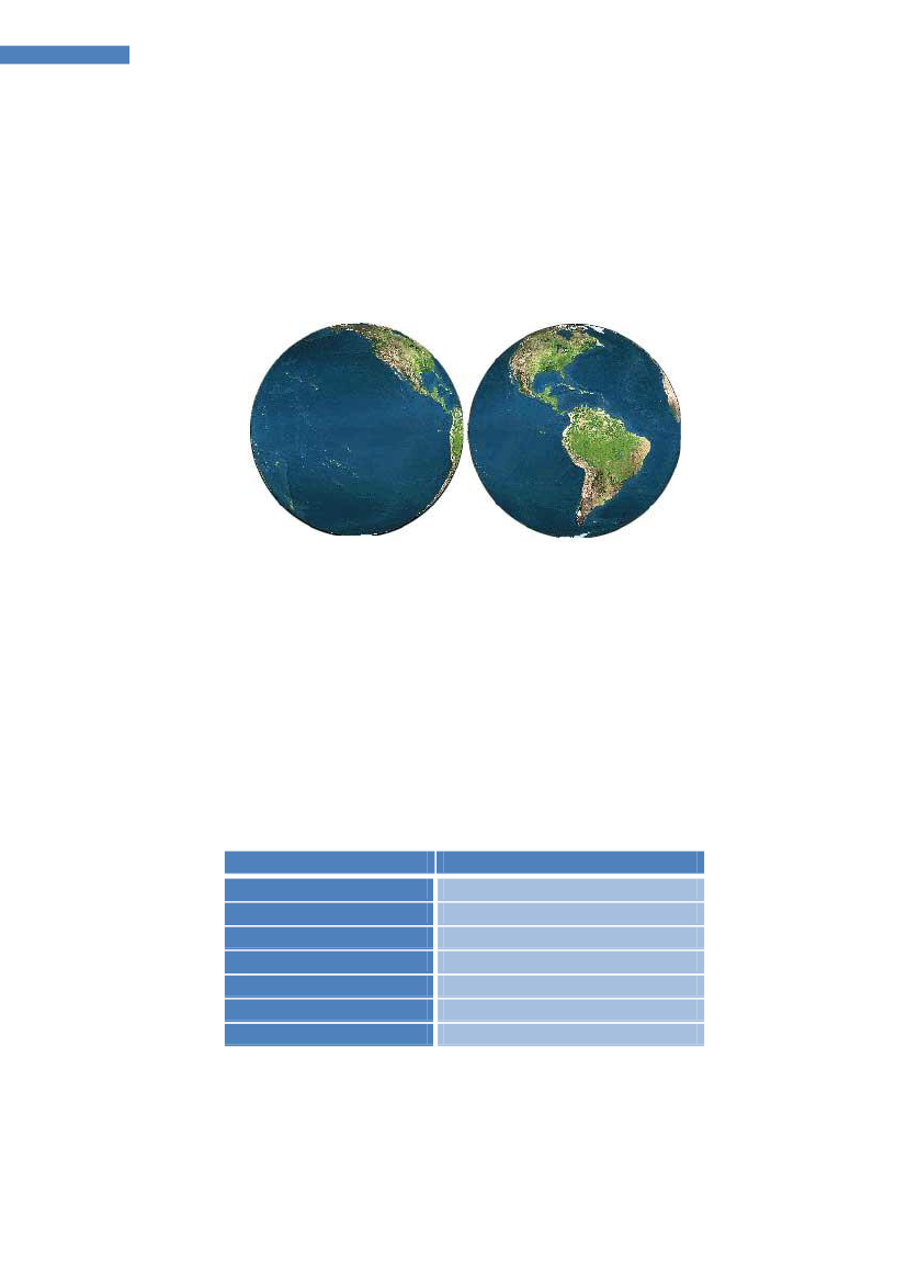
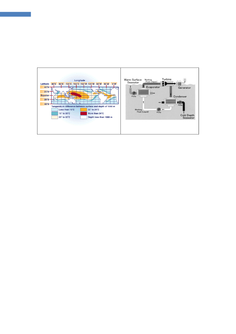
What is ocean energy?5.1 The Oceans Energy SourcesThe oceans cover about 70% of the globe and ocean energy can be harvested fromwaves, tidal variations and currents, ocean currents, temperature- and salinitygradients. From satellites, the waves, tidal elevations, currents and temperatures canbe observed.
Figure 1 The oceans cover 70% of the globe and can be monitored from satelliteshelping predict storms, wave and tidal conditions, as well as surface currents andtemperatures [w1]The annual energy potential from each Ocean Energy Source estimated in table 1 isbased on values produced for the ICCP screening report [1] based on information fromseveral sources. This indicates a total annual ocean energy resource of about 80.000TWh/yr.The global size of the Ocean Energy resource is roughly four times the globalelectricity demand which in 2008 was 16.819 TWh/yr and comparable to half of theprimary energy production which was 143.851 TWh/yr in 2008.Table 1 Global Ocean Energy Resources Estimates [1]Ocean Energy SourceWaveTidal (range & current)CurrentsThermal (OTEC)Osmotic (Blue energy)TotalAnnual Energy Resource29.500 TWh/yr8.000 TWh/yrN/A44.000 TWh/yr2.000 TWh/yr83.500 TWh/yr
The practical extractable amount of ocean energy (how much will be utilized) is aquestion of economy, environmental concerns, alternative options, and thedevelopment and demonstration of reliable ocean energy technologies leading topositive environmental impact.
Ocean Energy Technology Study, DanWEC 2012, revision 10-09-2012
6
Ocean Energy Technology Study
6
Prioritizing funding in the area of Ocean Energy
What types of Ocean Energy Technologies to focus on and how toprioritize R&D funding opportunities in the area?
From a European Ocean Energy Resources perspective, focus should be given totechnologies suited to convertWave, Tidal and Osmotic Power.The Europeanresource concerning Ocean Thermal Energy Conversion (OTEC) and Ocean Current islimited and therefore not considered relevant for Europe (see Annex I).To prioritize R&D opportunities, structured development protocols and guidelines needto be implemented within the European funding agencies. Independent experts will beable to give priority to which application should be funded, if they have a commonstructure and screening tool.Osmotic Powerhas the potential to provide base load supply, as it can be producedwhen needed. With a global potential of more than 1600 TWh/yr, where 10% is inEurope, it represents a new attractive business potential for both the commercialpower companies and technology suppliers.Priority should be given to thedevelopment of more efficient membranes to be included in the technology associatedwith conversion Osmotic.Tidal Barrage Energyhas a long history in Europe and earliest examples are datingback to 7th century in Northern Ireland. During the middle ages, tidal mills were widespread in Europe along the coasts of Scotland, Wales, UK, Holland, Belgium, France,Spain and Portugal (www.moinhosdemare-europa.org). The tides have not changedover the centuries, and they are still predictable in time, as periodic events of high andlow water level conditions twice a day.The 240 MW La Rance tidal plant, built in 1966, is producing about 600GWh/year. The254 MW Shiva project started operating 2011 in Korea. Discussions are ongoing in theUK for large tidal barrage projects, but environmental concerns have slowed down thedevelopment.Priority should be given to develop methods to create positiveenvironmental impact from barrage projects.Tidal Stream TechnologiesThere is number of different technologies underdevelopment for extracting energy from tidal currents. Some may appear similar tothose used for wind energy conversion, i.e. turbines of horizontal or vertical axis. Incontrast to wind energy, the tidal currents are predictable.With the present support structure in the UK, tidal stream technologies havedeveloped rapidly over the last decade with a number of large demonstration projectsin place in the UK and Ireland. It is likely that commercial forces will indicate whichsystems, technologies and installations principles are most suited to convert this verysite specific tidal stream resource.Priority should be given to monitor and validate the performance from a range ofconcepts in order to identify the most reliable and cost effective solutions forinstallation, maintenance, grid connection and station keeping of the tidal currentdevices. This includes gravity bases, pile structures, as well as floating structures fixedvia mooring lines and seabed anchors.
Ocean Energy Technology Study, DanWEC 2012, revision 10-09-2012
7
Ocean Energy Technology Study
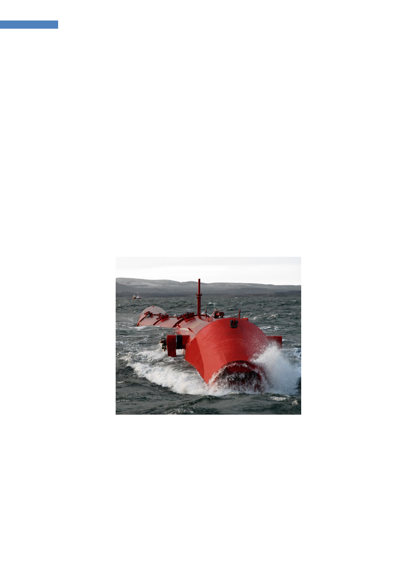
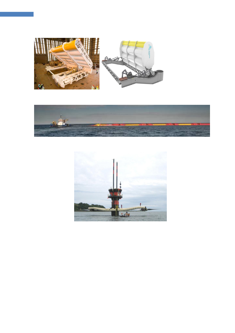
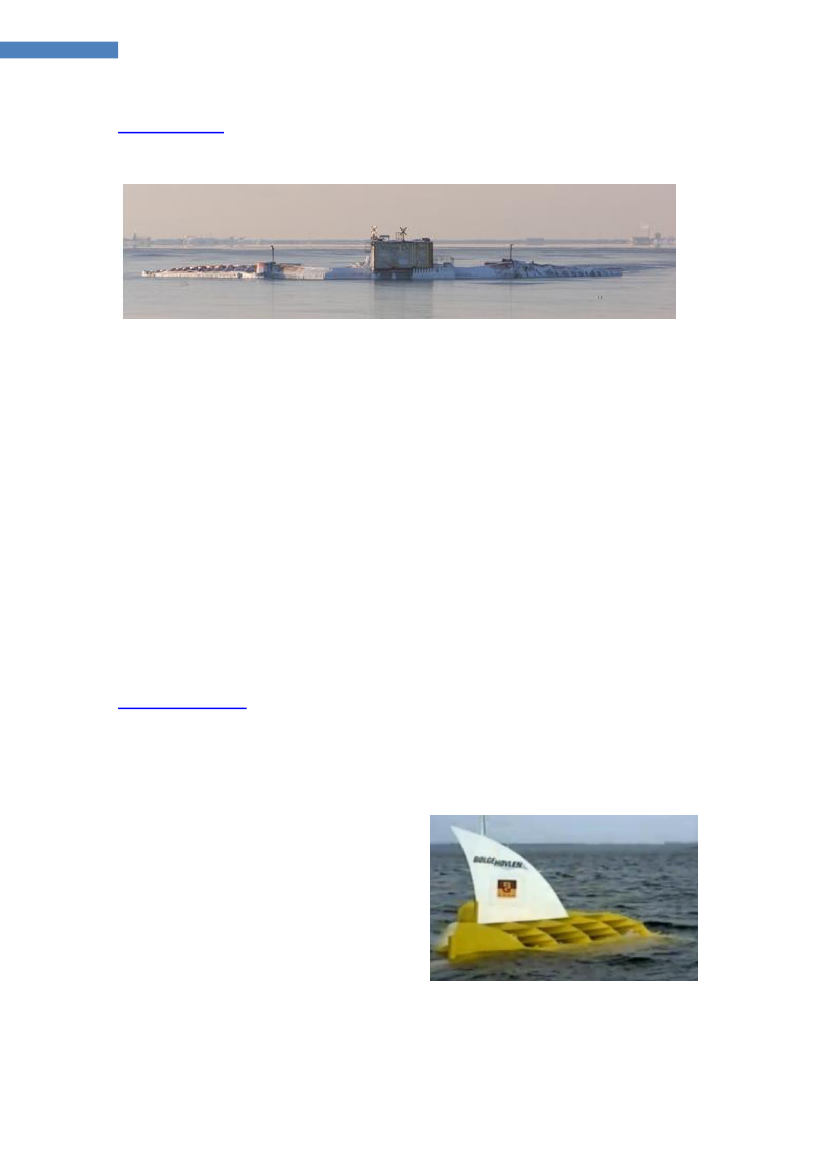
Wave Energyhas a global resource potential of 29.500 TWh/yr, where 10% is inEurope, and several European countries are facing coastlines with wave energy ofdifferent intensity per km coastline. There are differences from one country to the nexte.g. in terms of how far off the coast the water reach 50 meter depth, the seabed canbe of rock, sand, gravel or chalk. Some locations have large tidal height variation orcurrents whereas other locations do not. Some locations are covered by ice part of theyear. These differences are to some extend reflected in the large number oftechnologies proposed for converting the power of the waves.The Pelamis wave energy converter is today the most advanced off-shore systemdeveloped to a pre-commercial demonstration phase. Continuous development andsupport is required over the next 20-30 years, in order to develop more economicsecond and third generation wave energy conversion systems, as indicated in theroadmap from ETI [2](see Annex II).Wave energy converters deployed at sea today can be seen as front runners i.e.technologies that with dedicated development teams, governmental support andindustrial involvement and backup have been able to secure sufficient funding todevelop and demonstrate that wave power can work and produce power.In 2011, the first standards on how to measure and present the measured electricaloutput were developed under IEC-TC 114. Based on these standards, the powermatrices measured at sea can be compared to results obtained in laboratory scalesand simulated using numerical models, which will feed back into further R&D efforts.
Figure 2 Pelamis wave energy converter off the coast of the Orkney Islands [w2]Priority should be given to demonstrate a selection of different operating principles, inorder to identify the most efficient and reliable components, power take off systems,mooring systems, electrical interconnections and grid connections. In parallel, priorityshould be given to integrate the learning from these field tests into basic research,focused on new or improved principles, materials, components and systems leading tomore economic second and third generation devices.
Ocean Energy Technology Study, DanWEC 2012, revision 10-09-2012
8
Ocean Energy Technology Study
6.1 Research & DevelopmentDue to the increasing number of wave energy converter (WEC) concepts, more than100 are listed in the report by Thorpe [3]. Several initiatives have been taken tointroduce the structured development programs described for wave energy [4] and fortidal energy [5] and comparable procedures for development, as described inproceedings of the European projectEquimar[w3].In Denmark, several different WECs are being tested at sea and some are ready to bedeployed in larger scale at more exposed locations at sea. In response to thissituation, the Danish funding agency EUDP has funded an "industrial partnershipproject" with the objective:To find ways for developers to form partnershipsconcerning further research and development and increasing the value of investedfunding by sharing the results.The partnership project has been carried out during the period 2011 – 2012 andincluded interviews with the technology developers and joint workshops. The resultsshow that priory areas for joint development of wave energy conversion (in Denmark)are very similar to the priority areas identified under the ETI / UKERC Roadmap study[6] integrated in the European Energy Research Alliance’s (EERA) Ocean Energy JointProgramme (section 10.6).The priorities concerning wave energy development can be identified as:Guidelines and standardsPerformance guidelines and technical specifications(IEC-PT 62600 is currently addressing these issues)Device and system demonstratorsIn Denmark, the time is ready to build and install at least 3 near-full scale prototypesof the competing WECs before 2016. It is suggested that these systems are tested atsea at a common test site (Danish Wave Energy Center) where cabling and monitoringcosts can be shared.The ETI UK study suggests (see annex II):1st generation device and array sea trialsPerformance data collectionInstallation recovery methodsLow-cost O&M techniquesSubcomponentsCooperation and synergies between different technology developers and externalspecialized companies on development of vital common components and utilization ofexisting technologies to areas such as:Moorings (Foundations and mooring systems)Power Take-off (PTO) (Energy conversion system)Power cables to the floating power plants (umbilical / wet HV connectors)
New concepts and researchThis includes new devices and component development with a potential to reduce thecost of electricity. Tracking the Cost of Energy (COE) will be mandatory (in Denmark),combining a standardized design method with a verified energy performanceassessment (e.g. numerical and experimental).Development of toolsTools for resource analysis, design and optimization, device modeling, reliabilitymodeling, array design, interaction modeling and analysis.Ocean Energy Technology Study, DanWEC 2012, revision 10-09-2012
9
Ocean Energy Technology Study
6.2 Market stimulationPublic funding authorities will typically require matching private investment even atthis relative early stage of development.It is therefore proposed that a project specificfeed-in tariff based on the performance of the device (forsk-VE component inDenmark) is applied for future prototype testing.Such a performance based "feed-in" tarif will enable investors to have theirinvestment returned, if the prototype project operates according to a pre-specifiedperformance and maintenance scheme. Even if such project specific feed in tariffs arevery high compared to other sources of energy, it will help support and develop thebest systems, with a minimal risk for the public investment.Such a scheme should give the investors return of investments if the WECs, whichover a defined period of 2 to 5 years, have demonstrated performance, survivability,maintainability and reliability. Here after confidence will be sufficient to deploy alarger numbers of devices at pre-specified locations, incorporating whatever newknowledge established in the mean time.
6.3 Planning issues in different countriesIn Denmark exists a tradition for one-stop-shop concerning permits for powerproduction and deployment of WECs. This procedure is envied by colleagues e.g. inthe USA, where projects can be years delayed because of "blue tape" in the officialadministration. Several Danish WEC developers hold such temporary permits atdevelopment step 3 & 4 as described in section 6.It is recommended that within Europe, the possible locations of larger wave and tidalpower plants should be identified,with due respect to how the power from such sitescan be grid connected. Such information is necessary to define the wave resource,design conditions, deployment and grid connection costs, required to carry out theCost of Energy (COE) calculations.
6.4 Optimisation and learningThe development is not a straight forward process i.e. lessons learned should beincorporated and perhaps new discoveries also. For each individual project thedevelopment spiral can illustrate this.
Figure 3 Symbol for the development spiralTechnological development within wave energy is therefore recommended to continueat all levels from basic research to demonstration of prototypes and arrays. From aDanish view point wave energy systems are not ready today to be tested in Arraysuntil at least a few years of performance demonstration from a single prototype hasbeen accomplished, as indicated in table 2.
Ocean Energy Technology Study, DanWEC 2012, revision 10-09-2012
10
Ocean Energy Technology Study
The table below shows how the different stages of WEC development could beforeseen to development based on the strategy proposed in this report.The stages of WEC development are described in the reports from the OWEC-1 [7],the Danish wave energy program [8],Equimar[W3], and IEA-OES [4] and on page 22of this report.Table 2 Proposed development schedule for Wave Energy in Europe
This section is partly based on the methodology and outcome of the UKERC and ETIstudy, the Equimar project and the IEA-OES Annex II methodologies and the Danishpartnership project carried out between Danish wave energy developers andassociated companies, in which DanWEC has participated as an observer.The Danish Industrial Partnership Project led by Aalborg University was initiated inMarch 2011 and a first draft strategy report presented and discussed at a partnershipmeeting March 22, 2012 in Hanstholm, Denmark.
7
Reviews of studies of the most promising technologies
There are a number of studies concerning selection of the most promising technologieswithin wave energy and some of the most recent includes numerical models, in orderto calculate the wave energy converters performance.The conclusion from these studies is that so far there is no consistent way to predictwhich system for converting wave energy that eventually will take the lead. Even witha broad selection of different sizes, operating principles and locations, the results arenot significantly different according to [9]:The annual absorbed energy per characteristic mass was found to be in theorder of 1 MWh/tonne, whatever the device.
In order to identify the most promising technology, a more fruitful procedure can be totake the development forward in steps, as mentioned above, combined with checkprocedures for instance as described by the utilityESBI[w4].This readiness levels described includes a check-list at each step of development –such a check list could be helpful also in relation to public funding agencies concerningwhen the development is ready to move from one step to the next at the fundamentallevels until the developers are ready to enter into a negotiation with utilities.The incorporation of calculation of Cost of Energy – even in a simplified andstandardized form – can help identify and prioritize the areas that should be developedfurther i.e. a standardised Cost of Energy calculation tool in excel has been developedby Energinet.DK and can bedownloaded[w5].
Ocean Energy Technology Study, DanWEC 2012, revision 10-09-2012
11
Ocean Energy Technology Study
7.1
Recommendation
Development in steps combined with check points such as recommended by ESBI andcertification guideless by DNV, numerical and experimental verification, costcalculations such as recommended by IEA_OES and Energinet.dk.The Carbon Trust’s studies Future Marine Energy 2006 identified that the followingareas of innovation, as having most potential for cost of energy (CoE) reductions:•••Device components – Research into lowering costs and improving performanceof specific components in existing marine energy devices.Installation, operation and maintenance – Developing strategies to enablemarine energy devices to be installed, operated and maintained at a lower cost.Next generation concepts – Developing new device concepts that couldsignificantly lower the costs of marine energy compared to current frontrunners.
The Marine Energy Accelerator (MEA) [12] focused on these areas and concluded:
Adding innovation to the learning by doing curve significantly acceleratescost reduction relative to the baseline case.SurvivabilityThe MEA’s study on costs of wave energy has shown that to compete with otherrenewable energy technologies, wave energy developers will in the medium term needto exploit high energy sites. These sites generally also have larger extreme waves, sodevelopers must make sure that their devices are designed with survivability built in.Operations and maintenanceMEA’s analysis has also shown that operations and maintenance (O&M) costs make uparound a quarter of wave levelised cost of energy. This means that the developmentof efficient O&M strategies must be a priority. Examples in the following chapter showclearly that innovative O&M strategies or technologies can significantly reduce lifetimecosts at the device level, primarily by increasing the range of sea conditions in whichO&M can be undertaken, and by reducing the time required for operations. At thearray level, there are also opportunities for reducing O&M costs by developing efficientdeployment and recovery strategies for multiple devices, and by exploiting economiesof scale for planned maintenance. The simplest way to achieve low O&M costs is tobuild extremely reliable devices that need very little maintenance.Connection cost, and depthThe high baseline cost of wave energy also suggests that wave energy developers willneed to go relatively far offshore to energetic waters to generate competitively pricedelectricity. This will require particular focus on reducing the cost of cabling andconnection to the national grid, perhaps by simplifying procedures or by using lighterweight moorings or foundations and ensuring that devices can be installed in deepwater. If transit times to port are high, or if developers need to go far offshore toaccess good resources, the focus on reducing planned and unplanned maintenanceinterventions will be even more important.
Ocean Energy Technology Study, DanWEC 2012, revision 10-09-2012
12
Ocean Energy Technology Study
8
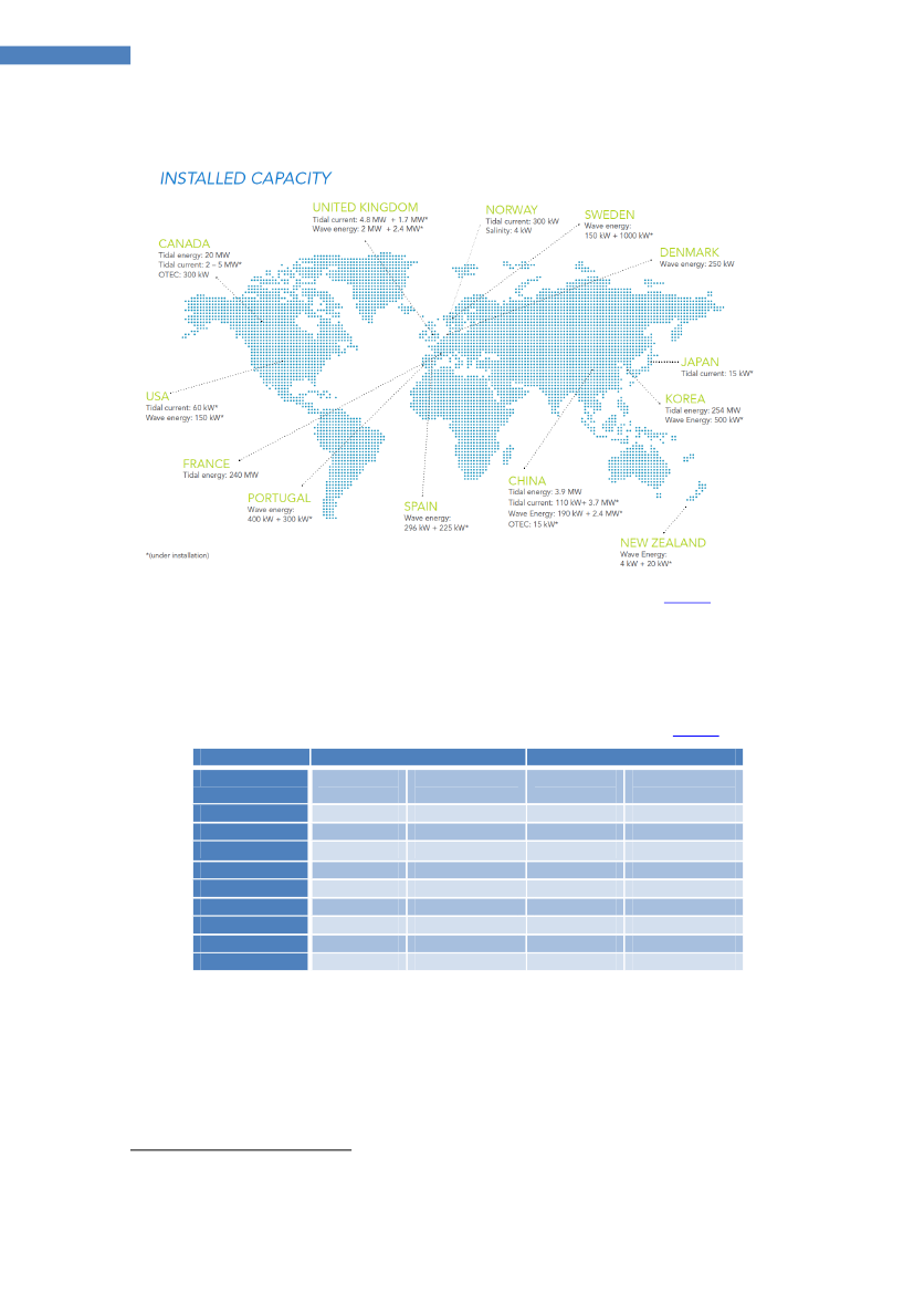
The status and potential of the ocean energy sector
Figure 4 Installed capacities of Ocean Energy Systems 2011[OES][w6]There are an increasing number of devices under development worldwide and theinstalled capacity of wave & tidal systems at sea is shown on figure 4 above. WithinEurope, the countries with installed wave and tidal energy systems are summarized inthe table below with indications of the targets in respective countries.Table 3 Status and targets of Wave and Tidal energy in Europe[OES][w6]Wave Power2011UKIrelandFrancePortugalSpainSwedenDenmarkStatuskW2000Target 2020MW500200300100StatusMW4,802402TidalTargetMW2.0001
800
400300150250
12
Target for combine wave and TidalLa Rance tidal barrageOcean Energy Technology Study, DanWEC 2012, revision 10-09-2012
13
Ocean Energy Technology Study
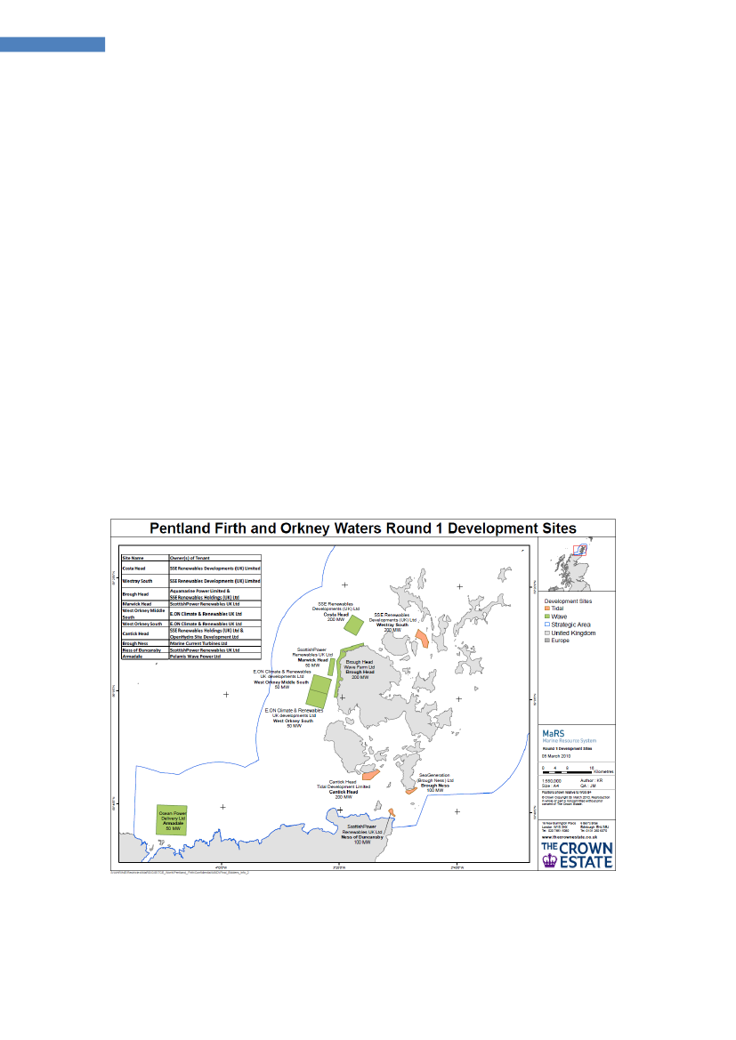
8.1 Status in selected countries8.1.1 The UKIn the UK, there is set a target for 2000MW Ocean Energy by 2020 and in March 2010the Crown Estate announced the names of the successful bidders for the world’s firstcommercial wave and tidal leasing round, for ten sites in Scotland’s Pentland Firth andOrkney waters. The leasing comprised 1200 MW of installed capacity of wave and tidalenergy developers for 2020, 600 MW from each.The developers who have signed a total of ten agreements for lease are:
Wave:• SSE Renewables Developments Ltd, 200 MW for Costa Head site• Aquamarine Power Ltd & SSE Renewables Developments Ltd, 200 MW forBrough Head site• Scottish Power Renewables UK Ltd, 50 MW for Marwick Head site• E.ON, 50 MW for West Orkney South site• E.ON, 50 MW for West Orkney Middle South site• Pelamis Wave Power Ltd, 50 MW for Armadale site.
Tidal:• SSE Renewables Developments (UK) Ltd, 200 MW for Westray South site• SSE Renewables Holdings (UK) Ltd & OpenHydro Site Development Ltd, 200MW for Cantick Head site• Marine Current Turbines Ltd, 100 MW for Brough Ness site• Scottish Power Renewables UK Ltd, 100 MW for Ness of Duncansby site.The sites are shown on the figure below:
Figure 5 Sites for wave and tidal energy projects in the UK announced March 2010[w7].
Ocean Energy Technology Study, DanWEC 2012, revision 10-09-2012
14
Ocean Energy Technology Study
Some of the technologies being developed in the UK are shown below.
Figure 6 The Aquamarine Oyster Device [w8] is presently being tested at the test siteEMEC in Orkney[w9]
Figure 7 The snake-like WEC Pelamis [w2]
Figure 8 Marine Current Turbines (MCT) SeaGen 1.2 MW installed in 2009 [w10]Testsite activity at the European Marine Energy Centre EMEC:Pelamis P2 750kW Machine (Commissioned by Eon)Pelamis P2 750kW Machine (Commissioned by Scottish Power Ren.)Aquamarine Power Limited – Oyster 800 Stage 1Wello Oy Penguin 500 kW wave converterOpen Hydro 250kW Open Centred tidal turbine deployedOpen Hydro – 600kW turbine deployed (not grid connected)Tidal Generation Ltd 500kW tidal turbine deployedAtlantis Resources Corporation AR1000 1 MW tidal turbine deployedScotrenewables SR250 floating tidal turbine deployedHammerfest Strom 1MW tidal turbine deployedVoith Hydro tidal turbine
Ocean Energy Technology Study, DanWEC 2012, revision 10-09-2012
15
Ocean Energy Technology Study
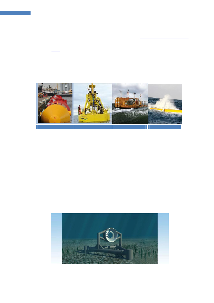
8.1.2 IrelandThe Government in Ireland has set a target of 500 MW Ocean Energy by 2020. Thegovernment has allocated €27m to be administrated by theOcean Energy DeploymentUnit[w11].The utilityESBI[w12] has actively been involved in Ocean Energy technology andresource studies as well as helping develop guidelines for Electrical connections. ESBIalso has a target of owning 150 MW of generation from the emerging area of waveand tidal energy in its portfolio by 2020. WestWave represents the third and final stepin the Irish Government’s Ocean Energy Strategy before commercial projects canbegin to achieve the Government’s target of 500MW by 2020. WECs investigated aspart of the West Wave project in Ireland:
Pelamis ( UK)
Wavebob
OE Buoy
Oyster
Figure 9 WECs included in the West Wave project [w2,w13,w14,w8]TheWest Wave Project[w15]WestWave is a collaborative project between the major players in the Irish waveenergy development sector, who share the common goal of putting Ireland at theforefront of ocean energy globally. The project brings technology developers,electricity providers and government bodies together to demonstrate how wave farmscan be built and operated in Ireland.WestWave aims to install and operate WEC's capable of generating 5 MW of cleanelectricity by 2015, while harvesting only a tiny fraction of the massive power hittingthe west coast of Ireland. By building a wave farm of 5 MW, the project willdemonstrate Ireland’s ability to construct, deploy and operate wave energyconverters. It will also pave the way for commercial projects, in terms of consentingprocedures, such as foreshore licensing, permitting, electrical grid access and localinfrastructure.The tidal stream technology Open Hydro project is based in Ireland.
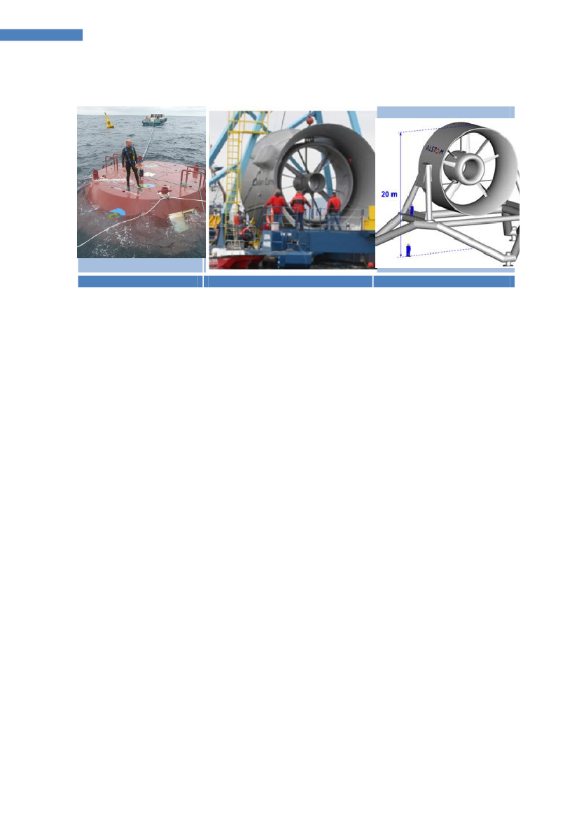
Figure 10 Open Hydro, Tidal energy system [w16]
Ocean Energy Technology Study, DanWEC 2012, revision 10-09-2012
16
Ocean Energy Technology Study
8.1.3 FranceFrance has set a target of 1000 MW of power from ocean energy by 2020.
CETO (Australia)
Open Hydro (IE)
BELUGA 9 (1 MW)
Figure 11 Wave and tidal systems investigated in France [w17, w16, w18]The EDF group,through its subsidiary EDF Energies Nouvelles, is running a waveenergy demonstration project, based on the CETO technology, a submerged pointabsorber moored to the seabed via hydraulic pump, off the coast of Reunion Island inthe Indian Ocean.The company responded to the NER300 call for tenders with a proposal for a 17MWtidal turbine farm, known as Normandie Hydro, and a 26 MW floating offshore windfarm, known as Provence Grand Large, both of them to be developed off the Frenchcoast. To assess the potential operating performance of tidal array systems, the R&Ddivision of EDF group builds on existing knowledge relating to the physics of the flowaround tidal turbines in order to account for the presence of a tidal farm in itsnumerical models.Alstomhas installed its ocean energy expertise centre in Nantes in the west of Franceand has deployed a fully dedicated team of 40 people to further develop, industrializeand commercialize the tidal technology. With a capacity of 1MW and a 13m turbineinlet diameter, BELUGA 9 [w18] will be the first commercial scale demonstrator to betested in 2012 in the Bay of Fundy, Nova Scotia, Canada.A second demonstrator with a bigger diameter, ORCA, is being developed,planned to be tested in 2013 in the French tidal test site of Paimpol-Bréhat.and
Test sitesThe SEM-REV [w19] onshore facilities were achieved by the end of 2011. Offices andtechnical facilities will be equipped in early 2012 and staff will start working full timeat Le Croisic town, which is the land base of the test site. A first contract has beensigned with the company SBM, which has publicly announced its funding from theFrench renewable energy organization ADEME.The SeaRev [w20] wave project was developed at University Ecole de Nante.
Ocean Energy Technology Study, DanWEC 2012, revision 10-09-2012
17
Ocean Energy Technology Study
8.1.4 PortugalThe target in Portugal is to install 300 MW wave power by 2020. Portugal hasestablished a high feed in tariff for wave energy and apilot zonefor testing up to250MW of WECs [w21].The first Oscillating Water Column (OWC) plant of 400 kW was built on the Azores PicoIsland in 1985 [w22], and since 2004 the plant has been run and operated by theWave Energy Center (WavEC). Portugal has adapted a politic that attracts developersfrom abroad to build wave energy plants in Portugal.In this way, the Dutch project AWS project carried out in Portugal from Porto, as wellas the first array of three 750 kW Pelamis wave energy devices in 2009. With EUfunding WaveRoller (Finland), OPT (USA), WaveBob (Ireland) and Wave Dragon(Denmark) have been attracted to explore opportunities for development in Portugal.
Pico OWC plant (PT)
Pelamis (UK)
AWS (NL)
OPT (USA)
Wave Bob (Ireland)
WaveRoller (Finland)
Figure 12 Portugal attracts foreign developers of wave energy[w22,w2,w23,w24,w13,w25]The utilities EDP and Energy Company Galp Energy are involved in Wave Energy inPortugal. EDP also holds a stake of €9 million in the wave-energy Agu§adoura project,which was launched off the Portugal coast with 2.25 MW in September 2009 composedof 3 Pelamis wave-energy converters.Technical University of Lisbon (IST)[w26], is doing research on floating OWCconverters, numerical work on the IPS buoy wave energy converter and a new type ofself-rectifying radial-flow air turbine.The Wave Energy Centre (WavEC)[w27], is a private non-profit association thathas been leading a European partnership designed to provide a high quality platformfor training young applied researchers in relevant areas of wave energy. TheWavetrain2 (2009-2012) follows the Wavetrain RTN (2004 – 2008).In addition, WavEC holds the secretariat for IEA-OES and have been partner in almostall European projects on Ocean Energy (see section 8.4).
Ocean Energy Technology Study, DanWEC 2012, revision 10-09-2012
18
Ocean Energy Technology Study
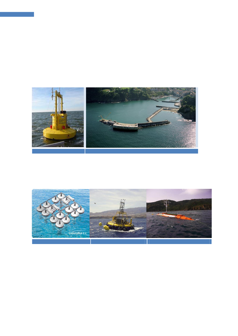
8.1.5 SpainSpain has a target of about 100 MW by 2020 to be deployed at sites in the Northernpart of Spain. Compared to other European countries such as UK, DK, NO, PT and SW,Spain is a relative new player on developing wave energy, but since 2005 Spain hasshowed a fast growing interest in this field.In November 2011, the 300 kW Mutriku OWC wave power plant was handed over toEVE (the Basque energy agency) [w28]. equipped with 16 air turbines from VoithHydro Wavegen and guarantees for performance and availability. The plant is housedwithin a breakwater at the port of Mutriku. During commissioning and acceptancetesting, the plant has produced 100MWh to the grid.
OPT (Iberdrola) [w24]
Mutriku OWC breakwater (Voith Hydro Wavegen Ltd)
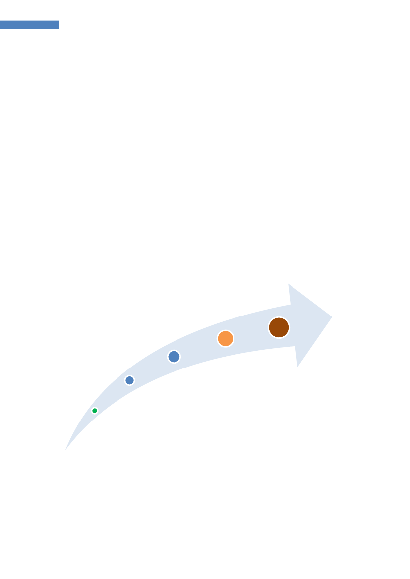
Figure 13 Spanish projects includes the 300 kW OWC Mutriku breakwaterOPT is interested in the Spanish market, and also three technologies shown belowwere investigated in the period 2008-10 co-ordinated by Tecnalia. The APC-Pisys isnow defining a project aimed to design, build and deploy a 1:5 scale wave energyconverter prototype during 2012.
Hidroflot (Spain)
APC-Pisys (1:5 scale)
OCEANTEC
Figure 14 Three technologies developed in one project co-ordinated by Technalia[w29,w30,w31]Test SitesThe Biscay Marine Energy Platform (bimep)[32], occupies a 5.3 km2 marked areaexcluded for navigation and maritime traffic, and located at a minimum distance of1,700 m from shore, close enough for fast access to deployed devices. The total powerof 20 MW is distributed over four offshore connection points of 5 MW each at 50-90 mwater depths. bimep is expected to commence operations in the last quarter of 2012.
Ocean Energy Technology Study, DanWEC 2012, revision 10-09-2012
19
Ocean Energy Technology Study
8.1.6 SwedenA marine spatial planning process of the Swedish territorial coastal waters is plannedto commence in 2012. Areas with potential for energy conversion by wave powerplants, if applicable, will be identified during this process.Sweden was a pioneer within wave power in the early 1970s and hosted the firstinternational symposium on wave energy in 1979 in Gothenburg. Since Mats Lejon andhis students at Uppsala University in 2002 started working on the “Point Absorber”,driving a direct electricity producing linear generator placed on the seabed, Swedenhas taken a renewed interest in wave power. In many ways, this Seabased systemcompares to the Danish Wave Power system developed and tested in the 1980s.The company Seabased [33] was formed in 2002 to develop the research at UppsalaUniversity related to linear generator wave power. During the period 2006 – 2011, theLysekil project was carried out focusing on ocean tests, generator and buoy design,and model development, including a 10-unit field research site including a submarineswitchgear and sea cable connection to load.In 2009, Seabased received funding for a pilot 10 MW project consisting of 420 floatsto be build at the Swedish west coast at Sotenäs municipality by 2015. The project isfinanced by state funding from the Swedish Energy Agency and the utility companyFortum. The objective is to verify that the technology can generate 25 GWh/yr fromwave climate off the west coast of Sweden.
Figure 15 Seabased, ready to bring wave energy to the world! [w33]Uppsala University has developed and tested a low speed marine current technology.A prototype project Minesto, including testing at Strangford Lough, Northern Ireland,has been funded by the Swedish Energy Agency.Test siteThe Ocean Energy Centre (OEC) [w34], connected to Chalmers University at theSwedish west coast near Göteborg, was established during 2011. The purpose of OECis to develop into a public-private sector platform that is able to support the appliedresearch of the growing number of developers in the region. OEC is currentlysupported by a regional grant.
Ocean Energy Technology Study, DanWEC 2012, revision 10-09-2012
20
Ocean Energy Technology Study
8.1.7 DenmarkDenmark today has some of the best documented wave power concepts in the world.This has been achieved with relatively modest funds, as the development of projectstypically has been carried out gradually scaling up and documenting the technologies.This has minimized the economic and security risks. A highly professional level hasbeen achieved through cooperation between research institutions, project developersand industry.The Danish Wave Energy Program is often referred to as a unique program in theworld and what was unique is that the program had a bottom up approach,implementing a development protocol, funding the projects at early stage with 100%and by doing so retaining the right to publish the performance and results in the publicdomain.The Danish Wave Energy Program, with a budget of 6 M€ over the period 1998 – 2001[8], focused on the first three steps of this development in which more than 40different ideas were tested at initial phase (step1), about 15 projects more elaboratetested at step 2 and onlythe Wave Dragon Projectreached step 3 within theprogram period, building a prototype of 20 kW for research and test at the benign testsite in Nissum Bredning.The development protocol described a procedure in which the WECs roughly could bedeveloped in five steps, where the WEC is gradually built and tested in larger andlarger scale – while design, components, power take-off and numerical and economicalcalculations are conducted with increasing accuracy. This development procedure isnot only technical, but evenly suitable for teambuilding, development of businessmodels and optimization of the technology underway.
Step 5Step 4Step 3Developmentand testing ofcomponents andprototype testingin the protectedwatersClose to full scalegrid-connectedexperiments forexample atDanWEC inHanstholmDemonstrationof wave energyparks consistingof multipledevices
Step 2Designoptimizationfeasibilitystudiesadditionalmodel tests inlarger scale
Step 1Basicresearchand modeltesting
Figure 16 The typical steps of wave energy development in DK.Each step has its own challenges and from successful completion of one step to thenext, the projects technological readiness level (TRL) increases, with a minimal risk interms of investment. If major design changes are considered or enforced, the devicedevelopment can shift back to the relevant step.
Ocean Energy Technology Study, DanWEC 2012, revision 10-09-2012
21
Ocean Energy Technology Study
The five steps are described below with examples of Danish projects at each step.Step 1:Concernsinitial testing of new ideas and concepts,typically it includesbuilding of a model representing the idea for initial testing in a wave flume or tank inco-operation with a university, typically Aalborg University (AAU) in Denmark. AAUhas in this way carried out numerous experiments with different concepts, anddocumented the results in a standardized report format. Some experiments haveformed the basis for PhD projects and development of new ideas. The tank testingprotocol further formed the basis for the first Annex II of the IEA-OES implementingagreement in [13, w35].Step 2:This concernsfurther development and laboratory testingof selectedconcepts, with a view to obtaining quantitative results for survivability and energyefficiency, etc., studies are carried out in wave tanks and typically combined withnumerical modeling. Of the 15 phase 2 projects, which was tested during the waveenergy program, described in the report [8], four of the initiated projects has sincethen been developed further in the Denmark. The SWAN dk3 project was based on theJapaneseBBDB conceptis now taken further in Japan and in Ireland – known as theOE Buoy[w14].Step 3: Prototype development and testingin the Danish practice has proven toinclude long-term testing of small scale pilot projects in protected sea areas, whilebusiness models and partnerships are developed and established.Wave Dragon[w36] was built in scale 1:4,5 and launched in 2002 and tested in the Danishsheltered site Nissum Bredning, until the ice winter 2009.Waveplane[w37] hastested a smaller prototype in Ringkøbing fjord for private funds. The project “Tusindben” was continued as theWavestar[w38] and during the period 2006 – 2010 it wastested at Nissum Bredning test site in scale 1:10, where it has produced data andpower. The project “Poseidons organ” has been developed further as aFloatingPower Plant[w39], built and tested at the offshore windmill park Vindeby in theperiod 2007-2011.Dexawave[w40] installed a small prototype in 2009 followed by alarger version installed at Hanstholm in 2011.Step 4 Demonstration in larger scale.This step includes the installation of a largerelectricity producing prototype in order to verify in detail its performance in realisticsea conditions.Wavestarbuild and installed a section of a 1.2 scale machine inHanstholm in 2009. Connected to the electricity grid this machine has producedelectricity to the grid over a two-year period. A special performance based tariff isagreed with Energinet.dk which is paid for the electricity or absorbed power producedin accordance with predictions.Step 5 Commercialization.To the extent that a project has documented its energyproduction and economics and contracted or sold one or more prototypes e.g. to anenergy company, the project has reached step 5. Presently, there are no Danishprojects that have reached this level.Test SiteWith the testing of Wavestar and Dexawave at Hanstholm the test site DanWEC[w41], situated at the west coast of Denmark, is in the process of building up itsinfrastructure to become a green lab and the site for future testing of WECs inDenmark at a scale somewhat smaller than required e.g. at EMEC, as described in theOES Annex II report [14].
Ocean Energy Technology Study, DanWEC 2012, revision 10-09-2012
22
Ocean Energy Technology Study
9
Challenges for selected Wave Energy Technologies
This section will describe some of the challenges associated with selected wave energytechnologies and with their application in relation to water-depth and distance to theshore, their mooring system and type of Power take-off system. This classification wasoutlined in the Offshore Wave Energy Project OWEC-1 [7].
Figure 17 Off-shore Wave energy converter study, OWEC-1 report 1996This section will give examples of selected WECs structured according to the locationwith respect to water depth, mooring and PTO type:1. Shore and near-shore bottom standing2. Off-shore taught-moored3. Off-shore slack-mooredThe first group is the most developed – apparently since the structure is fixed.The taught moored systems extract the energy relative to the seabed.The slack moored systems absorb the wave energy in a number of ways relative to orby the main structure itself and are typically installed on the deepest water depths.PTO systems being considered include:Pneumatic air turbines (single, manifold, closed or open systems)Hydraulics (oil or water-hydraulics, open and closed system)Linear electrical generators (of different types)Mechanical PTO (linear or rotational)
These possible combinations reveal that many variations of WECs can be expected. Inthe next section, the technological challenges associated with selected examples aredescribed. The challenges mentioned are based on the author's personal experiencefrom working with the development of wave energy over a period of more than 30years - and the future development will show how the developers will solve thesechallenges.
Ocean Energy Technology Study, DanWEC 2012, revision 10-09-2012
23
Ocean Energy Technology Study
9.1 Shore and Near-shore Bottom Standing Devices9.1.1 Shore-based OWCThere are a number of shore-based Oscillating Water Columns (OWC) WECs inoperation, on Islay in Scotland, the Pico plant on the Azores in Portugal, at the portMutriku breakwater in Spain, Sagata port Japan and OceanLinx Australia.
Pico Plant of 400 kW on the Azores in the middle of the Atlantic Ocean
WaveGEN 500 kW, Islay UKCourtesy of Voith Hydro Wavegen Ltd.
Mutriku 300 kW, WaveGEN SpainCourtesy of Voith Hydro Wavegen Ltd.
There are several types of air turbines considered suitable for OWCs at the momentand these are:Wells turbineDenniss-Auld turbine (Australia)HydroAirBi-radial turbine, (Portugal)
The unidirectional rotation of air turbine (Wells) was originally seen as the simplestway of converting the oscillating power from waves, due to the fact that the need forcheck-valves can be omitted and the structure thus constructed with less movingparts.The limited availability of suitable onshore sites with access to grid and infrastructuresuggest a limited long term potential for shore-based OWC. The OWC principle canalso be adapted on near shore tight moored structures as well as off-shore slackmoored structures.The shore based OWCs provide a valuable test bed with easy access to monitor anddevelop more efficient variable pitch turbines as well as gaining practical experiencewith the grid connection and operation of air turbine machinery.Ocean Energy Technology Study, DanWEC 2012, revision 10-09-2012
24
Ocean Energy Technology Study
9.1.2 Near-shore bottom standing converterTheWavestar[w38] installed at Hanstholm in Denmark holds deployment and powergeneration permit up to November 2013. The plant consists of two Ø5 m floats whichactivated by the waves move up and down and a hydraulic PTO system which drives agenerator that produces electricity. In cases of extreme conditions, the floaters arelifted out of the water and in even more extreme situations, the whole constructioncan be jacked up and down on four steel tubes, which are attached to a concretefoundation on the seabed.The principles of Wavestar was tested in Nissum Bredning in scale 1:10 before beingtested in larger scale and in a rougher environment at Hanstholm. The present testunit has a generator capacity of 80 kW and maximum measured an average poweroutput of around 40 kW. Daily and monthly summaries of production data arepresented online and these data forms the basis for a payment based on a projectspecific performance "feed-in" tariff agreed with Energinet.dk.During 2011,DanWEC[w41] introduced tours with the opportunity to visit Wavestarthat can be accessed via a 400-metre bridge leading to the structure from the shore.This has proved to be a unique way to promote an understanding of wave power forfamilies, companies, schools, and prominent personalities such as climate and energyministers as well as the Crown Prince of Denmark.
Figure 18 Wavestar in operation.Wavestar is involved in a number of development activities aiming at increasingenergy production and reducing costs. This includes the development of improvedcontrol strategies for the PTO, materials research (section 9.2) and participating in EUprojects with partners from the UK, Poland and Spain.Wavestar is developed based on a unique safety system, whereby it can lift thefloaters out of the water in storm situations. This feature has enabled Wavestar tosurvive in the harsh environment over several years so far. The challenge lies in howto develop more cost effective structures and a high efficient PTO system. Combinedwind and wave farms could provide synergies in relation to grid connections, use ofsea space, energy production and use of O&M personal. Wavestar has entered a co-operation agreement with the utility DongEnergy to investigate this issue further.
Ocean Energy Technology Study, DanWEC 2012, revision 10-09-2012
25
Ocean Energy Technology Study
9.1.3 Near-shore semi/submerged seabed mounted structuresOysterwas announced in 2001 by Professor Trevor Whittaker's team at QueensUniversity in Belfast. It is a structure fixed to the seabed and Oyster consists of a flap,moved back and forth by the waves. Power is taken out through hydraulic pumpsmounted between the flap and the structure pinned to the seabed. The companyAquamarine has been voted the best place to work in the UK and has guaranteedmillions of £ to the development of Oyster and the team of more than 60 employees.The latest generation Oyster 800 has an installed capacity of 800 kW. It has a width26m and height of 12 m and will be installed in a water depth of 13 meters approx.500 metres from the coast of Orkney at EMEC.
Oyster, Scotland[w8]
WaveRoller, Peniche Portugal, 2012.[w25]
The challenge that these submerged flap structures faces are related to the near-shoresites that they are supposed to operate in. At near shore conditions, deep-waterwaves becomes shallow water waves with increased horizontal motion of the water atthe seabed, eventually the waves break and the energy is dissipated.Introduced to the EMEC test conditions some years ago, it was mentioned as anexample to illustrate the roughness of the environment that huge rocks are thrown bythe waves onto the beach, and one can only refer to the wise words of professorStephen Salter: "buckets of water on your head hurt less than buckets of stones". Thissurvival issue is one of the major site related challenge facing the testing of Oyster.At the shore of Portugal, where the Wave-Roller system will be installed, theconditions are less rough and the perspectives for survival probably greater, but alsohere the submerged operations required for installation, inspections and maintenancewill be a challenge.
Ocean Energy Technology Study, DanWEC 2012, revision 10-09-2012
26
Ocean Energy Technology Study
9.2 Offshore tight-moored9.2.1 Taught moored Point absorbers reacting against the seabedIn Sweden and Australia, points-absorbers which exploit the movement relative to theseabed are explored — and where PTO is located on the seabed. The PTO of theSwedish absorbers is based on a submerged linear electrical generator, while theAustralian uses a submerged hydraulic PTO. The Swedish float is placed in sea areaswhere there are no tides, while the Australian buoy is operated just under the surfaceof the ocean, in order not to be influenced by the tide. The DWP point absorber testedin scale 1:4 off Hanstholm provided performance data over a period of 6 monthsduring 1995-96 [16]. A Norwegian point absorber, Bolt [w33], tested in Norway hasthe PTO on the surface.
Seabased 30 kW, Sweden [w33]
Ceto, 200 kW, Australia [w17]
Fred Olsen, Bolt 45 kW, Norway [w44]
DWP Point absorber, 1:4 Denmark
The advantage of these tight moored point absorber systems are that the costs ofmooring are incorporated in the Power Take-off and the footprint of the mooringtherefore relatively small. The challenge is to avoid the moorings be affected bysnatch loads and end-stop loads which can be associated with the characteristics andlimited stroke length of the PTO.
Ocean Energy Technology Study, DanWEC 2012, revision 10-09-2012
27
Ocean Energy Technology Study
Resen Energy[w45] has received financial support for the test of a new tight mooredprinciple "Lever Operated Pivoting Float" (LOPF), which is a principle developed in theUnited States that Resen has bought. The initial proof of concept has been carried outin the wave tank at Aalborg University.
Figure 19 Lever Operated Pivoting Float, AAU 2012Under the MaRINET programme Resen has applied to test a 2 kW unit in the deepwater tank of ECN in Nantes in France. The test is expected to take place in autumn2012, if EU authorization is given.The challenge for this point absorber on the initialstep – is to find reliable ways to transmit the electricity to the seabed.
Ocean Energy Technology Study, DanWEC 2012, revision 10-09-2012
28
Ocean Energy Technology Study
9.3 Offshore slack moored devices9.3.1 Heaving BuoysPoint absorbersA number of slack moored point absorbers shown in the figure below looks at thesurface almost the same as the tight moored point absorbers (section 6.2.1.).However, the OPT PowerBuoy and the WaveBob takes advantage of the relativemovement between a float and a submerged volume below sea level via a PTO.
OPT PowerBuoy, USA & UK (EMEC) [w24]
Wave Bob, Ireland [w13]
Figure 20 Slack moored point absorbersDesign of a mooring system with a small footprint and the development of a power-cable connection to the seabed, which can easily be detached when the system is duefor maintenance, are challenges associated with this type of devices.The use of linear hydraulic rams require that the hydraulic circuit is specially designedto deal with the typical unconventional high ram speeds required to obtain high pointabsorber efficiency. The typical lifetime of hydraulic seals is about 20000 km – whichwith an average travel of one meter per 8 seconds would be travelled in 5 years. Therams need some type of protection to prevent ingress of seawater that could rapidlylead to deterioration of the ram’s surface and loss of function.It appears that PTO systems based on hydraulics today, are not much more efficientcompared to the PTO based on air turbines.The slack-moored IPS Buoy developed and tested duringthe 1970s in Sweden was promoted as suitable test unitfor off-shore devices as part of the OWEC-1 project [7].During 2001-2007, the buoy was developed as AquaBuOYby AquaEnergy/Finavera USA/Canada. A prototype wasbuilt, installed and sank outside Oregon in 2007 –Finavera consequently stopped further development onthe project and consequently focused on wind energydevelopment.A revised version of the IPS buoy has been built andtested by WAVES4POWER [w46] in 2010 in Sweden - 40years after the first tests!
Ocean Energy Technology Study, DanWEC 2012, revision 10-09-2012
29
Ocean Energy Technology Study
9.3.2 Contouring structuresThese are structures floating horizontally on the surface of the sea, consisting of twoor more structures able to move relative to each other, such as a hinged raft and thepower is extracted from this relative motions by a PTO.For the period 2. July 2009 to August 2012,DEXAWAVE[w40] has received limitedpermission to establish a 6 meter wide and 13 meter long test-unit on 25 meter deepwater at Hanstholm in DenmarkDexawave is a slack-moored floating offshore converter and the test unit consists ofpontoons interconnected by flexible joints and the motion between the pontoonsactivates a hydraulic Power take-off system of 5 kW.
Figure 21 Dexa Wave being towed in place at DanWEC HanstholmDEXAWAVE is preparing the building of a larger unit of 250 kW. A small demonstrationmodel in scale approx. 1:10 was transported to Malta in 2011 and DEXAWAVE hasinstalled a wave-rider buoy to monitor the wave conditions and evaluate the businessopportunity Blue Ocean Energy �.The small scale DEXA experiment at the exposedlocation at Hanstholm showed that a revised mooring design was required and this ispresently being tested.CrestWing[w47] developed by Waveenergyfyn is based on a similar principle asDexa and holds a permission to test a prototype at benign site up to July 2012. The400 kg prototype is 2.44 meter wide and 10 meter long. The converter consists of twopontoons hinged together, anchored from the front pontoon to the seabed. Therelative movement between the two pontoons drives a mechanical PTO.
Figure 22 CrestWing Frederikshavn, September 2011The Crestwing demonstrated survivability at the benign test site, and the challenge isrelated to up-scaling the mechanical PTO.Ocean Energy Technology Study, DanWEC 2012, revision 10-09-2012
30
Ocean Energy Technology Study
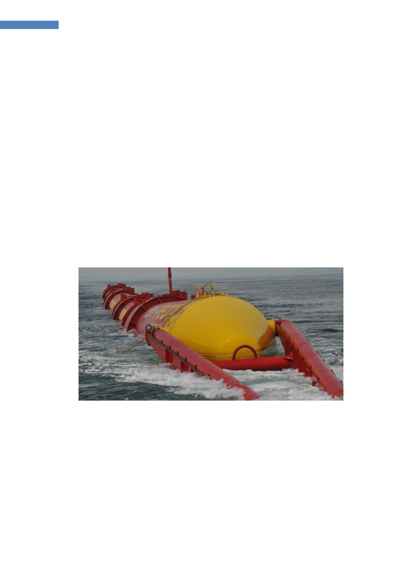
Pelamis-Wave Power,Pelamis [w2] is this year (2012) celebrating its 14thbirthdayand Richard Yemm, inventor and initiator of the project, writes on Pelamis home page:“It’s unbelievable how much Pelamis has achieved over the past fourteen years.When we started wave energy was an academic curiosity, and now we are animportant part of Scottish and UK Government strategy, have real machinesgenerating into the grid, and utility customers developing real wave farms off ourshores. From the first small tank test model in 1998 we have now designed, built andtested six full-scale machines and through that amassed a vast pool of knowledge andexperience that gives us unrivalled insight into what we need to do next to delivercommercial wave farms in the next few years. It has been a tough but rewarding 14years since our inception, and there is more than a tingle of excitement if I allowmyself to think where we may be in another 14 years’ time!”In March 2012, it was announced that Vattenfall signed up to take the last berth atEMEC in order to test a Pelamis machine in Orkney from 2014. “Weare working withVattenfall on a joint venture called Aegir Wave Power”,initially developing a 10MWwave farm off the coast of Shetland. Vattenfall also confirmed their intention to ordera single Pelamis machine later this year, depending on the progress of the Aegirproject.Pelamis inventor and founder Richard Yemm was awarded the prestigious Saltire PrizeAward Medal by the Scottish Government, which recognizes outstanding contributionsby individuals and groups to the development of marine power generation. (Pelamisnewsletter 2012-04-13)
Figure 23 Pelamis 2 During towing towards EMEC test site.The challenge facing Pelamis, as the most obvious candidate for further full scaledemonstration, is not only to survive the forces of the sea, generating power,reliability and maintainability – but also being able to deal with the pressure from allsides who want to see fast results.
Ocean Energy Technology Study, DanWEC 2012, revision 10-09-2012
31
Ocean Energy Technology Study
9.3.3 Overtopping and inflow systemsWave Dragon[w36] has been tested in Nissum Bredning since 2003 and the plant'selectricity generation license runs to 30. June 2012. The ice winter 2010 did, however,give a reason to end the tests, as shown in the below photo.
Figure 24 Wave Dragon on iceWave Dragon uses the overtopping principle, where waves wash up in a reservoirabove sea-level and water is discharged through a series of low head water turbinesoperating generators producing electricity. The plant tested had an installed power of20 kW and a weight of 237 tons. The prototype plant was 58 meters wide, 33 meterslong with a draught of 3.6 meters.Wave Dragon has submitted an Environmental Impact Assessment and application forconsent to install a pre-commercial demonstrator off the coast of Milford Haven,Wales.In 2011, Wave Dragon received support from the Danish funding agency EUDP toprepare a certified design of a full-scale 1.5 MW demonstration unit to the waveconditions at the test site DanWEC, Hanstholm. Furthermore, Wave Dragonparticipated in EU projects such as Wave-Net, CA-OE, WavePlam, Equimar, WavetrainI and II (and have presently still onewave-trainees employed).The challenge facing the Wave Dragon is the design of a reliable mooring system andthe power cable connecting from the device to the seabed.WavePlane A/S[w37] had since October 2008 permit for their facilities atHanstholm. The machine is a floating V-shaped design, with the stern against theincoming waves. The waves roles into funnels over an "artificial beach", and the wateris set in a rotating motion exhausted through turbines on each side generatingelectricity. Establishment permit expired in august 2009, and the plant is currently notin the test at sea.The unique feature of the Waveplane is itsability to stay calm in the waves, as theypass over and into the structure. Thisrequires a careful design, which had beenproven in smaller scales. This featurecould significantly reduce the loadings onthe mooring system.One of the challenges for WavePlane is tocost effectively to convert the low headflow of seawater into electricity.
Ocean Energy Technology Study, DanWEC 2012, revision 10-09-2012
32
Ocean Energy Technology Study
9.3.4 Floating OWC
Figure 25 OE Buoy, 20 kW, Ireland [w14]In Ireland, Ocean Energy is developing the OE Buoy. The buoy has been tested inscale 1:4 at the Irish test site in Donagal bay. The principle is a floating OWC inventedin Japan known under the name of BBDB. This BBDB principle on DHI was testedduring the Danish Wave Program of under the name Swan DK3 and ongoingexperiments are taking place at Saga University in Japan with variation of the concept.The backward bended column of water extending under the hull activates the airdriving an air turbine. Ocean Energy Limited has in 2012 landed a deal to grid-connectits first full-scale device at Wave Hub [w48].The challenge facing the OE-Buoy is the development of a reliable and affordablemooring system that will not influence the pitching motion of the device.Leancon[w49] received permission to establish an experimental scale model atNissum Bredning at a location approximately 200 m from the beach and approximately500 m from Nissum Bredning test site.
Figure 26 Leancon multi OWC systemThe prototype is a scale 1:10 model of a floating multi OWC-installations. The modelhas a weight of about 2 tons, manufactured in glass fiber. It is 24 meters wide and 11meters long. Top of the structure is about 1 m above the waterline. The model will beequipped with air turbine, generator and measuring equipment sufficient to evaluatethe performance and structural loads.The challenge facing Leancon is how to complete such a large project single handedwithin a reasonable time – the building and preparing of the large prototype is carriedout as a one-man project, down to the smallest details – it is indeed a challenge.
Ocean Energy Technology Study, DanWEC 2012, revision 10-09-2012
33
Ocean Energy Technology Study
AWS Ocean Energy UK,The AWS [w50] system brings back memories of the deviceknown as the Coventry Clam developed by Norman Bellamy during the UK waveenergy programme in the 70s [w51, w52].
Figure 27 The circular AWS flexible bag systemThe AWS device is a multi-cell array of flexible membrane absorbers which covertwave power to pneumatic power through compression of air within each cell. The cellsare inter-connected, thus allowing interchange of air between cells in anti-phase.Turbine-generators convert the pneumatic power to electricity.In full scale, a 2.5MW device will be slack moored in water depths of around 100musing standard mooring spreads, it will comprise 12 cells, each measuring around 16mwide by 8m deep, arranged around a circular 1300 tonne structure with a diameter of60m.Following tests with a 1:9 scale model in 2010, AWS is now working towards a full-scale 2.5 MW prototype of the AWS – III. In June 2011, Alstom broadened its marineenergy portfolio by taking a 40% stake of the Scottish company AWS Ocean Energy.The challenge related to this AWS technology is to demonstrate the reliability anddurability of the flexible membranes in order to avoid leakage.WEPTOS[w53] converter is under development in Denmark and was initially tested inSeptember 2011 in the Spanish test facility "Cantabria Coastal and Ocean Basin"(CCOB) [w54].
Figure 28 Weptos being tested in Spain September 2011(Photo:courtesy of Weptos)The floating wave energy converter is able to regulate the angle of the V-shapedconstruction, and thus reduce the impact and power absorption during rough weatherconditions. Along each of the two arms are a series of 20 floats with a geometryknown as "Salter's Duck", which draws on a mechanical PTO driving a common axlethat via gears drives the generators located in the stern of the machine.The model weighs approximately 1 ton approximately 12 meters wide against thewave front and each arm has a length of 7.5 metres.There is a challenge in the design of the mooring system and stern hinge design.
Ocean Energy Technology Study, DanWEC 2012, revision 10-09-2012
34
Ocean Energy Technology Study
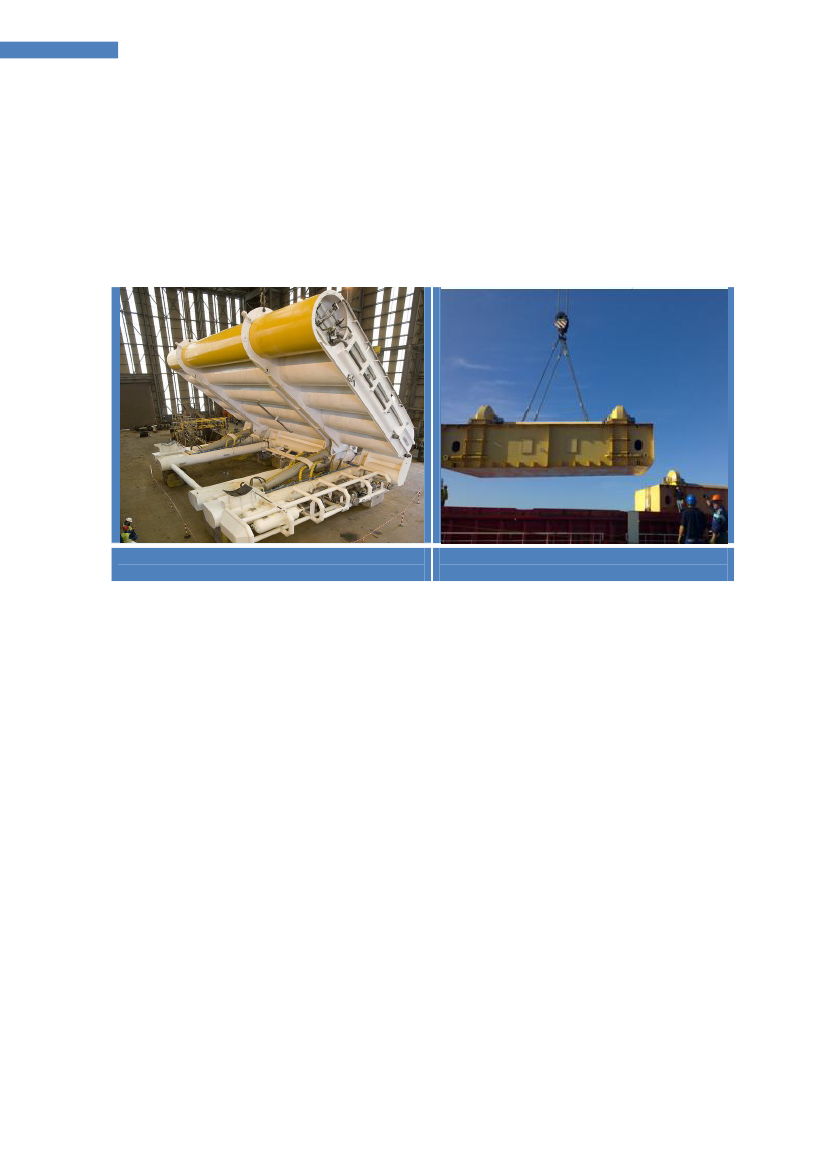
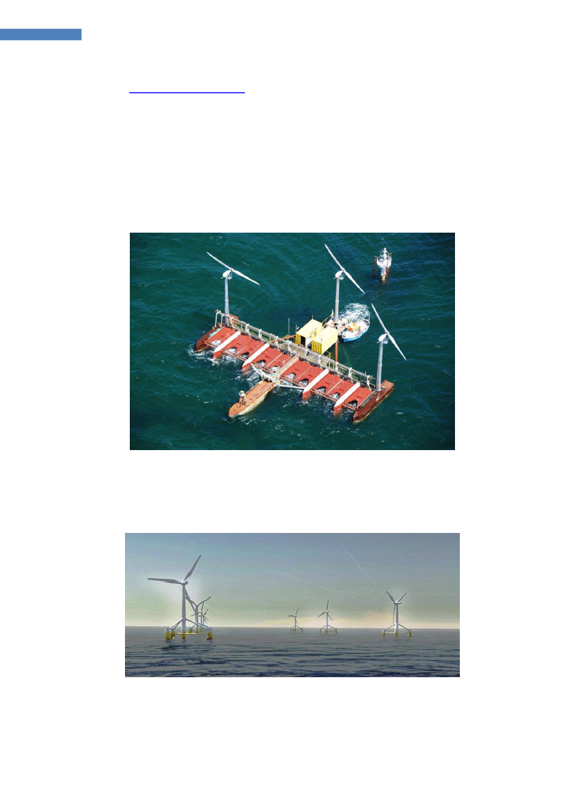
9.4 Combined solutions:In 2007,Floating Power Plantreceived deployment and generation permission totest Poseidon 37 at the benign test site at Vindeby until 31. March 2012.Poseidon 37 was installed in autumn 2008 and it is a floating offshore wave powerplant including three smaller wind turbines. The structure is 37 meters wide with alength of 25 meters and depth 3.5 meters. The plant is anchored to the seabed with apower cable connection to the outermost western wind mill in Vindeby sea-wind park.So far, only the power from the wind mills are transmitted.Floating Power Plant has established cooperation with Bridgeworks Capital in Oregonand created the company Floating power Inc. in the United States to commercializePoseidon's Wave/Wind energy platform.
Figure 29 Floating Power Plant [w39]The challenge for the FFP plant is to develop more effective PTO system to define theocean sites suitable for stable production of the combined power production of windand wave.
Figure 30 WINFLO [w55] floating off-shore moored platforms without wave energy willbe considerably more expensive compared to windmills placed on shallow watermonopoles, such concepts are studied by Ifremer.
Ocean Energy Technology Study, DanWEC 2012, revision 10-09-2012
35
Ocean Energy Technology Study
9.5 Common challenges for selected Wave Energy technologiesAs part of the Danish Industrial Partnership project [17] and as derived from the ETIStudy in the UKREC [6], a number of common technological challenges for wavepower conversion have been identified.In the order of importance, these areas are:further develop the mooring systemsfurther develop PTO systemsfurther develop electrical transmission from floating structure to the sea-bedmaterials and components
MooringsDevelopment of new mooring methods that with increased security and lifetime can beestablished at reduced costs compared to conventional mooring systems. This shouldinclude consideration to device size, extension to arrays, motions, power absorptionand how the device can sway around the mooring.PTO power electronicsA WEC typically includes smaller generators (less that 1 MW) and a challenge is to findthe most cost effective way and most appropriate power technology in order tointerconnect the generators of the WEC (AC/DC to AC converter on the WEC) and of a"farm" of WECs to a transformer station. This development would include theassessment of efficiency, price, maintenance etc.Power cable connectionThe development and testing of a flexible electrical cable connection, which can beused to connect a floating WEC, e.g. in such a way that it can turn around its mooringpoint to a fixed point on the seabed. It is a challenge closely associated with themooring method, the plant size, water depth, bottom conditions and met-oceanconditions.Material and componentsThere is recognition of the need to develop and test new materials and components onprototypes, in order to reduce costs and gain experiences regarding durability, anti-fouling problems, corrosion etc. from the testing. Sharing such experience can helpaccelerate the development.
Ocean Energy Technology Study, DanWEC 2012, revision 10-09-2012
36
Ocean Energy Technology Study
10 The industry, subcontracting industry and universitiesThere is a big industrial base of companies that possess competences relevant fordevelopment of wave energy – basically from the off-shore industry – but also fromthe wind energy industry.The process from R&D toward the market and operation involves a process in whichmany types of companies and industries will be involved as shown on the illustrationbelow.
Figure 31 Typical competences required in the development of ocean energy (courtesyof Wavestar)In the table below with examples of companies and industry within Europe associatedwith wave and tidal energy that can be found from, the published, UKERC ENERGYRESEARCH LANDSCAPE: MARINE RENEWABLE ENERGY [15], companies listed theWestwave project [w15], the Danish Industrial Partnership project [17] andcompanies mentioned on the feedback from developers, utilities and Universities. Thelist below is by no mean complete and can be updated i.e. by membershiporganizations such as the EU-OEA, from participant lists from conferences etc.Wave Energy TechnologyAquamarine LtdAWS Ocean EnergyCrestWing WaveEnergyFynDexaWaveFloating Power PlantFloating Power PlantLeancon Wave EnergyManchester BobberOcean Energy LtdOPTOreconPelamisWave PowerResen EnergiRolling cylinderTrident EnergyWave DragonWAVEenergy ASWavegenWavePistonWavePlaneWavestarIndustry and equipmentABBBam ContractorsBosh RexrothBPP TechFred Olsen LtdHarland and WolffHerbosch KiereIsleburnIT PowerKymaner Lda.LotusWorksNorvento EnerxiaOceaneering InternationalQinetiQRolls Royce Plc (Marine)Saipem SASeacore LtdTechworks MarineTension Technology InternationalTONNenergyVoith-siemensUniversity with test facilityAalborg UniversityEcole Centrale de NantesHMRC/University College CorkImperial CollegeLancaster UniversityNTNUQueen's University, Belfast.TUDelftUniversity of EdinburghUniversity of ManchesterUniversity of NewcastleUniversity of SouthamptonUniversity of StrathclydeUniversitiesCOVENTRYExeter UniversityFraunhofer IWESHeriot Watt UniversityInst Tecnológico de CanariasInstituto Superior Técnico
Ocean Energy Technology Study, DanWEC 2012, revision 10-09-2012
37
Ocean Energy Technology Study
WeptosCetoBoltSeabasedTidal Energy TechnologyEcopraxisLunar EnergyMarine Current TurbinesOpen HydroScot RenewablesSMD HydrovisionSwan TurbinesTeamwork TechnologyTidal Generation
KösslerConsultants EngineeringArevaArtemis Intelligent Power LtdAtkinsBlack & VeatchCummins GenerationEcofysEdinburgh Designs LtdEngineering BusinessGarrad HassanHalcrowInnovaytMartek LimitedMojo MaritimeRambøllSPOK APS
NUI MaynoothRobert Gordon UniversitySecond University of NaplesSwansea UniversityUCDublinUCL CIVILUniversity of BathUniversity of BristolUniversity of DurhamUniversity of NottinghamUniversity of OxfordUniversity of PlymouthUniversity of SheffieldUniversity of SouthamptonTechnical University MunichTechnical University Warsaw
UtilitiesAlstomDONG Energy Power A/SE.ONE.ONEDF EnergyEDP Inova§ãoEnte Vasco de la EnergiaESB InternationalFortumGuernsey ElectricityHydro TasmaniaIberdrolaNpower renewablesScottish renewablesScottish and Southern EnergySSE RenewablesVattenfallTest tanks facilitiesHR Wallingford LtdIfremer
CertificationDNVGerman LloydLegal matterPhilip Lee SolicitorsSandroos, advokatfirma
Network organisationsAOEARenewableUKBølgekraftforeningenDonegal County DevelopmentEsbjerg ErhvervsudviklingEU-OEAGreen-Ofshore AlliancenHanstholm HavneforumIEA Ocean Energy GroupIMERCLORCMEERMRIARenewable Energy AssociationWest Wave
Test sites at seaBimepDanWECEMECNaREC (Test Facilities)Nissum BredningSem REVWAVEHUB
Technological institutesDHIINETIMarine InstituteNUIG Ryan InstituteTECNALIA-RBTK
Public organisationsCarbon TrustDTIEnerginet.dkWestern Development Comm
Financial firms and banksOne51Pershing International NomineesScottish Enterprise Seed FundSigma CapitalTriodos BankVækstfonden
Ocean Energy Technology Study, DanWEC 2012, revision 10-09-2012
38
Ocean Energy Technology Study
11 International market trends within the Ocean Energy11.1 The technology trendsThe general market trends within ocean energy i.e. wave and tidal appear to be asfollows:Today, the UK has leased sites of about 1 GW power projected to be 40 GW by 2050.This represents a substantial market of thousands of devices constructed in watersaround the UK and elsewhere.The international market for tidal stream energy is developing faster compared towave energy, most likely because the tidal structures can be located at sites not tooexposed to extreme wave conditions with a good resource – and in this way they aremore directly related to the technologies used in offshore wind today.The rapid development of tidal stream technology is demonstrated by the manypromising device types at prototype stage operating at the EMEC test site [w9] suchas:1.2.3.4.5.6.7.Open Hydro 250kW Open Centred tidal turbine deployedOpen Hydro – 600kW turbine deployed (not grid connected)Tidal Generation Ltd 500kW tidal turbine deployedAtlantis Resources Corporation AR1000 1 MW tidal turbine deployedScotrenewables SR250 floating tidal turbine deployedHammerfest Strom 1MW tidal turbine deployedVoith Hydro tidal turbine
In addition, there is the 1,2 MW Seagen located in Northern Ireland [w9].
Concerning wave energy, the UK sites for about 600 MW has been leased and theWECs currently being tested at EMEC are:1.2.3.4.Pelamis P2 750 kW Machine (Eon)Pelamis P2 750 kW Machine (Scottish Power Renewables)Aquamarine Power Limited – Oyster 800 Stage 1Wello Oy Penguin 500 kW wave converter
Based on the successful completion of these EMEC tests, the WECs will be testedfurther in arrays to be deployed at the Wavehub site in southern UK.
Ocean Energy Technology Study, DanWEC 2012, revision 10-09-2012
39
Ocean Energy Technology Study
11.2 Implementing Agreement on Ocean Energy Systems (OES)The international trends within ocean energy development is best followed on thehome page for the Implementing Agreement on Ocean Energy Systems [w56] initiatedby Portugal, Denmark and the UK in 2001.As of December 2011, 19 countries are members of the OES: Portugal, Denmark,United Kingdom, Japan, Ireland, Canada, the United States of America, Belgium,Germany, Norway, Mexico, Spain, Italy, New Zealand, Sweden, Australia, Republic ofKorea, South Africa and China.The annual reports produced by the OEC and their website are informative and up todate.Trends within ocean energy can be monitored at dedicated conferences such as:European Wave and Tidal Energy Conference (EWTEC)International Conference on Ocean Energy (ICOE)4thGlobal Marine Renewable Energy Conference (GMREC)
These conferences tend to get bigger and bigger.
11.3 Maritime Spatial PlanningIn the annual report from the OES 2011, [w6] there is an interesting article on theneed for Maritime Spatial Planning and the conclusions are referred below:Maritime Spatial Planning (MSP) will have significant implications for the developmentof marine renewable generally, and the ocean energy sector in particular. Economicdevelopment and marine environmental protection have an equal weighting in theEU’s Integrated Maritime Policy and both elements are either already specificallyaddressed in legislation or will be in the near future. This means that it is essential forthe ocean energy industry to engage fully in the Maritime Spatial Planning process toensure that conflicts are minimised and that the industry can progress in a sustainablemanner. From an industry perspective, it is essential that research is undertaken tounderstand the extent to which ocean energy developments can be deployed and co-located with other users of the sea. This could help lessen the need for ‘exclusionzones’ within MSP systems.As a key player in the advancement of ocean energy, the Ocean Energy SystemsImplementing Agreement (OES) is in a unique position to encourage device andproject developers to involve themselves in the debates and processes surroundingdevelopment of Maritime Spatial Planning systems in different jurisdictions. TheEuropean Commission recognized that stakeholder participation will significantly raisethe quality of MSP. Developers already have a wealth of tacit knowledge from theirexperiences of deploying devices. They know what has worked well and where. Thistype of knowledge will help inform the creation of an MSP system that is both fullyreflective of the needs of the industry and will also enlighten other industries as to thespecific requirements of the ocean energy sector. The OES should promote this activeinvolvement of the sector, as it is an essential criterion for progress and acceptance ofMSP.
Ocean Energy Technology Study, DanWEC 2012, revision 10-09-2012
40
Ocean Energy Technology Study
11.4 Standards under IEC TC 114On the technical side, standards on ocean energy are being prepared under the IEC TC114 [w57] including so far:IEC TC 114ReferencePTPTPTPT62600-162600-262600-1062600-100TitleTerminology.Design requirements for marine energy systems.Assessment of mooring system for marine energy converters.Power performance assessment of electricity producing waveenergy converters.Wave energy resource assessment and characterization.Power performance assessment of electricity producing tidalenergy convertersTidal energy resource assessment and characterization.Wave Energy Converter Power Performance Assessment at aSecond Location Using Measured Assessment Data.
PT 62600-101PT 62600-200PT 62600-201PT 62600-102
11.5 Certification of Tidal and Wave Energy ConvertersDNV has a risk-based certification process for tidal and wave energy converters. Thisprocess is defined in their OSS-312 Certification of Tidal and Wave Energy Converters.The OSS-312 informs a generic list of documents and defines the extent of the scopeof certification. The certification is not only related to safety and environment, but tofunctional requirements that are of key importance for the success of marinerenewables.The certification process is a gradual process that evolves at the same level as thetechnology evolves. This is reflected on the different certification deliverables, as partof the initial steps of the certification process and its function of the results from thetechnology assessment and failure mode identification and risk ranking; i.e. it is adirect function of the criticality and associated risks to the success of the technology.
11.6 The EERA initiativeOne of the aims of the EERA Ocean Energy Joint Program [w58] is to promote theincorporation of ocean energy into the SET-plan. The EERA Ocean Energy JP will alsoprovide a coordinated voice towards the European Commission and the member stateson medium to long term research priorities that are required in order to bring thesector to successful commercial deployment levels.The EERA Ocean Energy JP is based around six key research themes. These themeshave been developed based on existing research roadmaps which identify the criticalareas of research required for the successful growth of the industry.The research themes are:••••••ResourceDevices and TechnologyDeployment and OperationsEnvironmental ImpactSocio-economic ImpactResearch Infrastructure, Education and Training
Within each research theme, a number of sub-topics have been identified as key longterm research objectives.
Ocean Energy Technology Study, DanWEC 2012, revision 10-09-2012
41
Ocean Energy Technology Study
Initial EERA Ocean Energy JP activities are not able to cover all of the objectivesidentified but have been prioritized in the first year’s program by need and the currentavailability of funding. The gap between, what has been identified as a key long termobjective, and what the EERA Ocean Energy JP is actually able to deliver in the firstyear, will help identify issues that need future funding and coordinated researchefforts.A key objective of the joint EERA program is to address the medium to long termresearch challenges that the sector has identified in a variety of ocean energyroadmaps such as the European Ocean Energy Association’s Oceans of EnergyRoadmap (2010) [], the UK DECC Marine Action Plan (2010) [w59], the ScottishFREDS Marine Energy Roadmap (2009) [w60], the UKERC/ETI Marine EnergyTechnology Roadmap (2010) [w61] and the UKERC Marine Renewable EnergyTechnology Roadmap (2008) [w62]. The challenges identified in these roadmaps arestrongly reflected in the six key EERA ocean energy research themes.Members of the EERA are as of March 2012 are: Germany, Italy, UK, Ireland, France,Spain, Portugal, Norway and Denmark is in the process of joining.
11.7 European projects on Ocean EnergyWavePlam (2007-2009)[w63] - The purpose of the WAVe Energy PLAnning andMarketing project is to develop tools, establish methods and standards, and createconditions to speed up introduction of ocean energy onto the European renewableenergy market.EQUIMAR(2008-2011) [w3] – "Equitable Testing and Evaluation of Marine EnergyExtraction Devices in terms of Performance, Cost and Environmental Impact", EU 7FPfunded (STREP programme).SOWFIA (2010-2012) [w64] - “Streamlining of Ocean Wave Farms ImpactAssessment” aims to facilitate the development of European wide, coordinated, unifiedand streamlined environmental and socio-economic Impact Assessment (IA) tools foroffshore wave energy conversion developments. Wave farm demonstration projectswill be studied in each of the collaborating EU nations.FAME (2010-2012) [w65] - “The Future of the Atlantic Marine Environment” - financedby the EC INTERREG IV programme, with the aim to link the protection of naturalvalues, specifically biodiversity (avifauna) with economic activities at the EuropeanAtlantic Ocean.Aqua-RET2 (2009-2011) [w66] - “Dissemination activities and transfer of technologyin the ocean energy sector” (EU - Leonardo da Vinci - Lifelong Learning Programme).ORECCA (2009-2011) [w67] - The goals of the ORECCA project (Off-shore RenewableEnergy Conversion Platforms – Coordination Action) are to create a framework forknowledge sharing and to develop a roadmap for research activities in the context ofoffshore renewable energy that are a relatively new and challenging field of interest.CORES (2008-2011) [w68] - “Components for Renewable Ocean Energy Systems”. EU7FP funded (RTD programme). This project concentrated on the development of atoolbox of the wave to wire simulations to be applied to the OE Buoy Technology,developed by the Irish company Ocean Energy Ltd.WAVEPORT (2009-2012) [w69] - “Demonstration & Deployment of a CommercialScale Wave Energy Converter with an Innovative Real Time Wave by Wave Tuning
Ocean Energy Technology Study, DanWEC 2012, revision 10-09-2012
42
Ocean Energy Technology Study
System” (EU FP7 programme), with the aim to demonstrate a large scale gridconnected, 600kW peak rated, Powerbuoy Technology.SURGE (2009-2011) [w70] - The European Project SURGE (Simple UnderwaterRenewable Generation of Electricity) is funded by the EC under FP7 and intends to testand assess the second generation of the Finnish WaveRoller device, near Peniche.After testing the prototype WaveRoller1 at full-scale at the European Marine EnergyCentre (EMEC), in Scotland and in Portugal, AW-Energy, owner of the technology, willinstall and test its second prototype in Portuguese waters.MaRINET (2011-2015) [w71] - The aim of this project is to coordinate research anddevelopment at all scales (small models through to prototype scales from Laboratorythrough to Open Sea tests) and to allow access for researchers and developers intofacilities, which are not universally available in Europe.TROPOS (2011-2015) [w72] - “Modular Multi-use Deep Water Offshore Platform forHarnessing and Servicing Mediterranean, Subtropical and Tropical Marine and MaritimeResources”. The aim is to develop a floating modular multi-use platform system foruse in deep waters.MARINA(2010 - 2014) [w73] the MARINA Platform project will establish a set ofequitable and transparent criteria for the evaluation of multi-purpose platforms formarine renewable energy (MRE).H2OCEAN(2012 – 2014) [w71] H2OCEAN is a project aimed at developing aninnovative design for an economically and environmentally sustainable multi-useopen-sea platform. Wind and wave power will be harvested and part of the energy willbe used for multiple applications on-site, including the conversion of energy intohydrogen that can be stored and shipped to shore as green energy carrier and a multi-trophic aquaculture farm.MERMAID(2012 – 2015) [w72] Innovative Multi-purpose off-shore platforms:planning, Design and operation. Marine structures for offshore wind farms andaquaculture have to be installed at various sites and on much larger scale than earlierimplementation of offshore structures in order to fulfil EU strategies (1) for reductionof fossil-based energy and (2) to become a major player in sustainable aquaculture.However the feasibility is much more sensitive to the costs of structures and theinstallation of the structures than for instance Oil & Gas facilities.Both for offshore renewables and for aquaculture a substantial part of the costs isvariable cost related to operations and maintenance of the plants. It is obvious thatoptimization of the use of ocean space for different purposes might benefit fromshared resources such as staff allocation, transportation of staff and material from andto the platforms, use of forecasting systems, ships etc.
Ocean Energy Technology Study, DanWEC 2012, revision 10-09-2012
43
Ocean Energy Technology Study
12 Selected examples of cooperation and synergiesFuture development of the ocean energy sector will be linked with developments inother sectors, such as offshore wind energy, exploiting positive synergies intechnology developments (e.g. components), infrastructure, supply chain and policies.There will be significant opportunities for co-location of technologies; for example,ocean energy and offshore wind energy, utilizing common platforms or wave/wave orwind/tidal hybrid systems. Mutual learning processes, shared infrastructure andinnovations from a shared supply chain will be of great benefit to the future expansionof both the ocean energy sector and related sectors
12.1 European Wavetrain 2 Project
01.01.2009–30.06.2012The first example of synergies between different actors being mobilized within theOcean Energy industry is the Wavetrain program. Over the last decade, the Wavetrainprogram co-ordinated by the Wave Energy Centre in Portugal has been successful inbringing different companies together and integrate graduate students into theresearch and development sphere of Ocean Energy.The Wavetrain2 project is a multinational Initial Training Network (ITN) funded underthe FP7-People program, in order to face the wide range of challenges that industrial-scale wave energy implementation faces in the near future, focusing on technicalissues, from hydrodynamic and PTO (Power Take-Off) design, to instrumentationissues and energy storage and cost reduction which are critical for successfuldeployment. On the other hand, also non-technical “barriers”, typically less tangibledifficulties related to legal issues (licensing, conflicts of use, EIA procedures, gridconnection, regional differences) and the non-sufficient representation of socio-economic benefits of the sector, is dealt with, as they are seen as a major obstacle forfast implementation on a European scale. The network consists of 13 Europeanpartner institutions and 17 associated entities, from research units and devicedevelopers to project developers and consultants.
Figure 32 Wavetrain2 fellowshttp://www.wavetrain2.eu
Ocean Energy Technology Study, DanWEC 2012, revision 10-09-2012
44
Ocean Energy Technology Study
12.2 Float 2 Case story:
Hi-Con, Wavestar and Aalborg University
The Float project was initiated by the developers of Wavestar, Dexawave and Hi-Con acompany that works almost exclusively with High Performance Fibre ReinforcedConcrete in order to test a new concept of wave energy floaters, made of Ultra HighPerformance Fibre Reinforced Concrete.The preliminary proof-of-concept study carried out during 2011 headed by Hi-Conincluding Aalborg University and Wavestar and Dexawave and the conclusions of thepreliminary study confirmed the possibility of significantly reducing costs for the forthe WS converter through application of UHPC. However, the study also demonstratedthat for the DexaWave converter, the UHPC did not prove as a viable option for theircylindrical floaters.The focus of the FLOAT2 project which started 2012 is to utilize the synergies anddemonstrate a new concept for wave energy floaters, made of Ultra High PerformanceFibre Reinforced Concrete (UHPC) on the floaters for Wavestar as an enablingtechnology for more competitive wave energy production.
Figure 33 Wavestar investigates floaters of UHPC [w73]
Ocean Energy Technology Study, DanWEC 2012, revision 10-09-2012
45
Ocean Energy Technology Study
13 Information exchangeThe request for information has been send to the organisations indicated in the tablebelow and the response and information received has been helpful and is greatlyappreciated.CompanyContactQuestionguide send2012-03-092012-03-092012-03-092012-03-092012-03-092012-03-092012-03-092012-03-092012-03-09
Informationreceived2012-03-162012-03-122012-03-302012-03-122012-03-14mail2012-03-13
Interview
Danish developers:WavestarenergyFPPDEXAWave DragonCrestwingLeanconWeptosWave PistonRoling cylinderLaurent MarquisAnders KrøhlerLars ElbækErik Friis-MadsenHenning PilgaardKurt D RasmussenTommy LarsenMartin von BülowInventua ApsLars IngerslevRichard Yemm,Chris RetzlerCharlotte TaylorMats LeonJochem WeberMike WhelanSimon GrayTore GulliGreg AllanTom HeathPeter Frigaard,Jens Peter KofoedAlain ClementAurélien BabaritAntonio SarmentoGareth ThomasBrian HolmesTony LewisStephen SalterTrevor and CuanJorgen HalsTorgeir MoanPer HolmbergBjorn BolundJon VindahlKringelumDavid FutterJohanna YatesClaudio Bittencourt2012-03-16
2012-03-142012-03-13
Developers abroad:Pelamis WaveOyster, AquamarinSeabasedWavebobOE-bouyAWSBoltCETOWaveGen2012-03-122012-03-272012-03-122012-03-122012-03-122012-03-122012-03-122012-03-292012-03-272012-03-092012-03-092012-03-092012-03-092012-03-092012-03-092012-03-272012-04-26
2012-03-202012-03-312012-04-272012-04-2012-03-142012-03-122012-04-062012-04-112012-03-14
UniversitiesAAU,ECNITS,UCC HMRC,UEDIN,QueensNTNU
2012-04-062012-04-26
UtilitiesVattenfall;DONG,ESBIE-on,Scottich renewable,DNV2012-03-092012-03-092012-03-282012-03-272012-03-282012-03-212012-03-212012-03-122012-03-22
2012-04-09
Ocean Energy Technology Study, DanWEC 2012, revision 10-09-2012
46
Ocean Energy Technology Study
12.1
Utilities
DONG Energy represented by Jon Vindahl Kringelum, ESB Ireland represented byJames Tedd and Vattenfall Per Holmberg and Bjorn Bolund have responded to ourquestionnaires, and their responds to each question is summarized below.HOW IS THE SCREENING OF THE OCEAN ENERGY MARKET DONE?DONG Energyis following the development of Ocean Energy, including availablesupport regimes within their geographical focus area (NW-Europe). DONG Energy isespecially interested in technologies that have synergies with Offshore Wind and isonly focusing on wave currently.In that respect DONG Energy is looking at available wave resource near their existingand future wind projects and the available resources in general.On the technical side DONG Energy do screening of wave concepts internally, but notwith any fixed frequency.ESBhas used a dedicated technical evaluation process (See WestWave Supply ChainAppendix 2 at http://www.westwave.ie/contact_us/) to determine a TechnologyReadiness Level (TRL) for each technology.A hurdle of TRL8, which requires at least a single prototype of the machine to havebeen deployed and operated, has been set as the maturity required to be a candidatetechnology for WestWave the early array project ESB are leading.ESB have also provided technical support to technologies at TRL 5-7 through supporton Safety, Power Quality, Electrical Engineering etc.Vattenfallhas since 2006 screened the ocean energy technology options in terms oftechnical readiness. Vattenfall’s strategy is to engage with those technologies that areapproaching readiness for wave farm deployment, and fit their business requirements.The level of engagement increases with readiness.Early stage technologies (TRL4-5) are continuously monitored by Vattenfall usingvarious means such as conferences, relevant newsletters and home pages. For thosetechnologies that are more mature, Vattenfall (TRL5-6) have also regularly been indirect contact with the technology developers to receive and review their material. Asthe developers approach readiness (TRL6-7) Vattenfall requests specific technicalinformation based on their template to evaluate technically. Once Vattenfall havedecided that a technology will likely become viable they contract the firm to allowtechnical due diligence and propose projects. This has happened with one company.Vattenfall also has close contact with other stake holders such as authorities and tradeorganizations mainly in UK but also in the rest of Europe.
Ocean Energy Technology Study, DanWEC 2012, revision 10-09-2012
47
Ocean Energy Technology Study
WHAT TYPE OF CONCEPTS RECEIVES SUPPORT AND WHY?DONG Energyhas partnership agreements with 2 Danish concepts, but are notproviding any financial or investment support.1. Floating Power Plant, where Dong Energy is supplying infrastructure forconnection to their Vindeby Wind Farm2. Wave Star, where the company has an R&D partnership agreementESBwork closest together with the companies who have developed their conceptsclosest to commercialization.Vattenfalldecided at an early stage to focus on deep water wave devices as theyjudged the potential to be large and the consenting process easier (i.e. scalability). Asa utility Vattenfall is a procurer and operator, i.e. not developer, of technology andtherefore mainly interested in wave power converters in advanced stages ofdevelopment. As of now Vattenfall is collaborating closely with Pelamis ltd. that intheir judgment has a sound technology as well as being the most mature concept froma development perspective. Vattenfall is also following the development of a numberof deep water concepts that are promising.REQUIREMENTS FOR VALIDATION/DEMONSTRATION SCALE?DONG Energyis in general open to participate in demonstration projects, however atthe moment they are focused on their 2 existing partnerships. Demonstration at theirexisting sites requires a track-record of prior successful offshore testing and a veryhigh level of safety, both regarding personnel and the device itself.ESB:There is a need for public funding to bring technologies through to a stage whereutilities such as ESB can be involved. This includes all the stages up to TRL 8, and atthat stage grant and tariff support is required.Vattenfalluses a Technology Readiness Scale (TRL) with 9 levels (from idea=1 tocommercial readiness=9). Preferably Vattenfall would like to see concepts proven infull scale in operational conditions (TRL 8) but acknowledging the immaturity of thesector the company takes active interest at an earlier stage. Generally Vattenfall'sminimum requirement is for the concept to have been proven in the sea in, say 1:10to quarter scale, with power generation (TRL 6-7). Vattenfall also expect thedevelopment to have followed the preceding steps with e.g. validation ofhydrodynamic performance through both tank tests and numerical modeling.PROSPECTS OF INCLUDING OCEAN ENERGY IN YOUR BUSINESS PLANDONG Energy:Wave Energy is currently not a part of DONG Energy's business plans.To achieve that, Devices developers have to prove a long continuous period of energyproduction offshore without major failures or unavailability. Also there must be aproven and documented prospect of driving down the Cost of Energy to a competitivelevel.ESBhas an Ocean Energy Team with the target to develop the capability to deliverUtility Scale Ocean Energy Projects. In the short term ESB is leading the WestWaveproject to deliver Ireland’s first grid connected 5 MW wave energy array.Vattenfallalready has an ocean energy business plan, since 2006, as part of its R&DProjects portfolio. If the development can fulfill Vattenfall's requirements on technicaland economic performance Vattenfall expect wave power to be a future part ofVattenfall’s renewable energy portfolio.
Ocean Energy Technology Study, DanWEC 2012, revision 10-09-2012
48
Ocean Energy Technology Study
WHAT PERCENTAGE OF FUTURE ENERGY PRODUCTION WILL COME FROMOCEAN ENERGY?DONG Energy:This is not possible to say at the moment.ESBI:There is great potential on the western seaboard of Europe for generation fromOcean Energy. There have been numerous studies on this which would be the bestreferences to use.Vattenfall’socean energy business plan models 1000MW and 500MW deploymentscenarios by 2030. The achievement of these scenarios is entirely dependent ondevelopment of the technology and market enablers. We cannot predict the installedcapacity beyond 2030. Vattenfall’s overall electricity production is currently in theorder of 180TWh.
Ocean Energy Technology Study, DanWEC 2012, revision 10-09-2012
49
Ocean Energy Technology Study
12.2
Universities
This section includes the response to our questionnaires from António Sarmento IST inPortugal, Alain Clement and Aurélien Babarit at Ecole Centrale de Nantes (ECN) inFrance, Garreth Thommas at University College Cork (UCC) Ireland, Peter Frigaard atAalborg University (AAU) in Denmark and David Forehand at University of Edinburgh(UEDIN)WHAT THEORETICAL AND NUMERICAL TOOLS ARE USED TO MODEL THEPOWER PRODUCTION FROM WAVE POWER DEVICES?IST:The state-of-the-art are time-domain models based in the linear theory toestimate the forces due to wave-structure interactions. However these models usenon-linear sub-models to simulate the performance of the electromechanical powertake-off equipment and the control laws. Most often the mooring forces are alsotreated linearly (quasi-static). In the most advanced state-of-the-art models theimpulse response functions needed to include the memory effects of the wave-structure interactions are replaced by state-space approaches. Non-linearhydrodynamic models for the wave-structure interactions exist but are no standard(and require much more simulation time). Overtopping devices are typically moredifficult to model as the overtopping is a high non-linear approach, which is simulatedby empirical formulae.ECN:It depends on the desired level of accuracy:1.To make a quick and dirty estimate of the power absorption of a particularWEC, we will make use of the typical Capture Width Ratio (CWR) for the category intowhich falls the WEC. Basically, we will identify the working principle of the WEC, willlook in the table in [Babarit and Hals, 2011] and based on the characteristic length orwidth of the device, we will calculate the power.2.A more refined approach will be to develop a numerical Wave to Wire (W2W)model, the wave structure interaction being modeled using linear potential theory. Itwill make use of one of the usual BEM solver such as WAMIT, Aqwa, Aquaplus, … Moredetails can be found in [Bhinder et al., 2010]3.For modeling specific details, CFD codes might be requested. However, wedon’t believe that they are suitable for assessing the power production from wavepower devices. Mostly because of CPU time, but also because it is well known thatthere have issues with propagating accurately gravity waves.UCC:Wammit, Mathlab (simulate toolbox), Mathematica, Numerical wave tank, Survilconditions simulated using CFD Second order – non-linear models.AAU:Simple dynamic models. Wamit, Shipbem, CFD programmes like CFX, Fluent,Star, Open Foam, Naval Foam etc…UEDIN:Firstly, I should state that I am only talking about numerical models that areused in Edinburgh University, other numerical models also exist.From a hydrodynamic point of view, we use the commercial frequency-domain codeWAMIT to model the response of both single and multiple devices.This is aradiation/diffraction code which assumes linear (Airy) waves and small body motions.Using hydrodynamic data from WAMIT (wave excitation and added mass and dampingcoefficients), an in-house, time-domain, hydrodynamic WEC array model has beendeveloped at Edinburgh. This code can model transient behaviour and allows theinclusion of nonlinear external forces, such as nonlinear PTO and mooring forces. Thetime-domain model uses a state-space approach to replace the difficult radiationconvolution terms.
Ocean Energy Technology Study, DanWEC 2012, revision 10-09-2012
50
Ocean Energy Technology Study
Edinburgh University researchers are also members of the international Wave EnergyConverter Array Network (WECAN). This network of researchers has recently writtena review paper on numerical hydrodynamic modelling techniques for arrays of waveenergy converters but it also applies to individual devices. The title of this reviewpaper is “A Review of Numerical Modelling of Wave Energy Converter Arrays” and itwill be presented at the OMAE conference held in Rio de Janeiro, Brazil in June 2012.The time-domain array model developed at Edinburgh has also been incorporated intoa larger Edinburgh wave-to-wire model.This wave-to-wire code can simulatedirectional, irregular seas. In addition, it can model hydraulic PTOs in each device aswell as the offshore and onshore electrical network. The model is truly bi-directional,in that disturbances in the sea can be seen in the electrical network and vice-versa.HOW WELL CAN YOU ENSURE MODEL ACCURACY (E.G., BY USINGLABORATORY TEST/WATER TANK/WAVE BASINS)?IST:The state-of-the-art numerical simulation models are relatively accurate in smallwaves but not so much in high waves, it being critical for survivability conditions(extreme waves). In those cases non-linear and possibly viscous models need to beuse. In very resonance conditions (sinusoidal waves close to the resonance frequencyleading to very large device excursions) state-of-the-art models are also not accurate.ECN:W2W model must be validated against scale model tests. In ECN, a large wavebasin is available (50m long, 30m wide, 5m deep, 48independent wavemakers) forthat purpose. Usual scale is 1/10 to 1/20 to validation tests.ECN References:1.A. Babarit, J. Hals, 2011. On the maximum and actual capture widthratio of wave energy converters. In Proc. Of the 9th European Wave and TidalEnergy Conference, Southampton, UK.2.M. Bhinder, M. Guerinel, M. Alves, A. Sarmento, A. Babarit, 2010. Stateof the art Report WP1 – Numerical Hydrodynamic Modeling of Wave EnergyConverters. Deliverable D2 of the Wavetrain2 EU projectUCC:Viscosity, important, in small scale. Pretty good todayon in the basin. Several scales, suggest to incorporatemodeling with experiments to get a feeling of the accuracy.intend - using model tests. Marinet, course on how tosystems,in measuring what's goingas a standard numericalDo you simulate what youmodel test wave energy
AAU:The answer depends on the scale and the purpose of the testing.In a typical testing in scale 1:30, forces like mooring forces can be measured and upscaled with an accuracy better than plus/minus 2%. Overtopping can be measuredand up scaled with an accuracy better than plus/minus 5-10%. Energy production(including control systems) is typically the big problem. If the PTO system is simplyscaled, a typical accuracy can be as low as plus/minus 30%. Therefore PTO systemsare normally not just scaled but modeled in such a way that their effects onmovements are modeled correct.UEDIN:The results of the hydrodynamic time-domain array model have been testedagainst those of WAMIT for situations where both approaches are valid (i.e. “steady-state” oscillations). The results of the hydrodynamic time-domain array model are alsogoing to be compared against tank test results. Edinburgh University researchers arepart of a European team who will be performing tank testing on arrays of model waveenergy devices in DHI’s wave basin later this year. These test have been entitled“WECwakes” and they are being funded by EU’s Hydralab IV programme.
Ocean Energy Technology Study, DanWEC 2012, revision 10-09-2012
51
Ocean Energy Technology Study
12.3
Standardisation / certifying authorities
Concerning Standardisation and certification DNV has been contacted, represented byClaudio Bittencourt who has provided the information below.LEVEL OF DOCUMENTATION CONCERNING MAIN REQUIREMENTS FOR OCEANENERGY DEVICESDNV has a risk-based certification process for tidal and wave energy converters. Thisprocess is defined in our OSS-312 Certification of Tidal and Wave Energy Converters.The OSS-312 informs a generic list of document and defines the extent of the scope ofcertification. The certification is not only related to safety and environment, but tofunctional requirements that are key for the success of marine renewables.Thus, the documentation required for certification is related to the wide range ofaspects (from load derivation and interaction between power take-off and structuralresponse to power performance). Nevertheless, this documentation is no different towhat the developer / designer needs to generate to define and confirm satisfactoryperformance of the technology.The extent and depth of documentation required is confirmed on a technology bytechnology basis as part of the initial steps of the certification process and is functionof the results from the technology assessment and failure mode identification + riskranking; i.e. it is a direct function of the criticality and associated risks to the successof the technology.The certification process is a gradual process that evolves at the same level as thetechnology evolves and this is reflected on the different certification deliverables. TheOSS-312 will be revised soon, but the process described there and principles are stillvalid.SPECIFIC REQUIREMENTS FOR WAVE ENERGY TECHNOLOGIESThe main specific requirement is to perform the initial steps of the certification processthat involves the definition of the certification basis (i.e. all elements that defines thelimitations and boundaries of the technology and what are its targets), technologyassessment (for identification of degrees of novelty of the technology) and the failuremode identification and risk ranking (that allows to identify what are the failuremodes, how critical they are and what is necessary to do to deal with them, i.e. tomitigate the risks).As there is a large diversity of concepts for wave energy conversion, there is no singleor simple specific special requirements that can be highlighted except for the fact thatthe needs to the certification process are related to the assurance of the overallperformance of the technology.Naturally, for floating devices (wave or tidal) there are special attention to be paid toexport power cable, the mooring analysis (considering the power take-off), fatigueaspects, corrosion stability and water tightness, installation methodology andderivation of power performance.
Ocean Energy Technology Study, DanWEC 2012, revision 10-09-2012
52
Ocean Energy Technology Study
Appendix I Sources of Ocean EnergyWave EnergyWave energy [w74] is the energy contained in the waves generated by the wind onthe surface of the sea and the associated motion of the ocean extending down belowthe sea surface down about a quarter of a wavelength.Not surprisingly, the largest wave recourses are found on the middle of the northernand southern hemisphere where the winds are strongest. Waves generated in onelocation can on deep water travel long distances with little loss of energy, until wavesapproach shallow water regions and coastlines where the energy is dissipated, throughbottom friction and wave breaking and power levels reduce.The annual average wave power level in kW/m on different locations can be seen onthe map Figure 34.
Figure 34 Average annual Wave Power levels expressed in kW/m in the Oceans(Oceanor)Waves are predictable from weather forecasts. Based on satellite information andmeteorological models, the wave conditions at a certain location can be predicted withreasonable accuracy about 6 – 8 hours in advance.Finally, the wave energy resource can be harvested not too far off the coast of manycountries as can be seen on the map. In fact, the length of the coastline multipliedwith the power level can help give an estimate of the wave energy resource.Even though waves appear similar, the wave conditions at selected location can bequite different in terms of the statistical distribution of sea-states. Some ocean areassuch as the North Sea is dominated by steeper waves compared to the waves furthersouth such as off the coast of Portugal where the waves are dominated by swells, asdescribed in the OES -Task 2.1 report [14]. The highest waves at the site, the sitespecific tidal variations and current conditions must be considered in the design of theapplied ocean energy technology.
Ocean Energy Technology Study, DanWEC 2012, revision 10-09-2012
53
Ocean Energy Technology Study
Tidal EnergyTidal energy [w75] is the energy associated with the tides created by the relativeforces and motions between the sun, moon and earth and the rotation of the earth.The tides are therefore predictable in time, as periodic events visible in terms of highand low water conditions once or twice a day.Associated with the tidal water level variation are tidal streams or currents which canhave significant speeds depending on location. Tidal Streams are characterized by highmaximum speed (more than 2m/sec) and by changing direction once or twice a daydepending on the location and tidal variation at the site. Tidal energy can be utilizedby tidal barrage - or tidal stream systems.Tidal Barrage•Tidal barrage systems that utilize the difference in water level variation duringhigh and low tides in combination with dams and reservoirs.There are a definite number of sites where tidal barrages can be build, in connectionwith natural estuaries, the most well known is the La Rance 240 MW plant in Francewhich has been in operation since 1965. In Korea, the Shiwa 250 MW tidal plant isunder construction and other sites such as Bay of Fundy in Canada and the Severn inthe UK under consideration.Tidal Stream•Tidal Stream, systems that convert the flow of water – much like windmillsconvert the flow of air.Tidal stream sites are often found at places where the speed of water flow is increasedby local bathymetry and narrow sounds between islands.
Locations with high tidal variations
Concentrated tidal streams locations
Figure 35 The potential sites for Tidal energy within Europe is located in the UK,Ireland, France and Norway [w66]
Ocean Energy Technology Study, DanWEC 2012, revision 10-09-2012
54
Ocean Energy Technology Study
Ocean CurrentsOcean currents are very characteristic flow patterns in the oceans. Some of thesecurrents are created and driven by the winds and some by the differences in waterdensity. Compared to tidal streams, the ocean currents maintain the same directionand their speed is typically much lower and therefore expected to be more expensiveto convert into electricity.Surface CurrentsThe world’s prevailing winds help bringing the warm air from the equatorial zonestowards the poles. The winds create giant circular currents patterns in the majorocean basins (like gyres). Subtropical high-pressure areas (at around 30� latitude)drive these gyres. Coriolis forces cause water in motion to be pulled to the right in thenorthern hemisphere and to the left in the southern hemisphere.
Figure 36 Major Ocean Surface currentsDeep Ocean CurrentsCurrents created by differences in water density are sometimes called the ocean“Great Ocean Conveyor Belt.” This circulation helps transporting heat from the equatortowards the poles, as shown on figure 5, and as such other vital principle of nature.Cold or salty water is denser and sinks, whereas warm or less salty water is less denseand rises. In Polar regions, much of the ocean water is tied up in ice sheets. The saltremains in the liquid water, so the water in these areas is very salty, as well as verycold. This water is consequently very dense and sinks. It is replaced by water fromlower latitudes. The deep, dense water then moves slowly across the ocean floor andeventually rises in warmer latitudes.
Figure 37 Great Ocean Conveyor Belt [w76]
Ocean Energy Technology Study, DanWEC 2012, revision 10-09-2012
55
Ocean Energy Technology Study
Ocean ThermalOcean Thermal Energy Conversion (OTEC) [77] is in principle the same as a heatpump i.e. a system that generates power using the temperature difference betweenwarm and cold water. OTEC works best when the temperature difference between thewarmer, top layer of the ocean and the colder, deep ocean water is more than 20�C.These conditions exist in tropical areas, indicated on the map below.
Figure 38 Temperature difference between surface and 1000 meter depth an exampleof a closed cycle OTEC converter.Cold water is typically more than 1000 meter below the surface and OTEC plantstherefore require a long intake pipe to bring up the cold water to the surface. With atemperature difference of 20 degrees and a flow of 1 m3/s, an OTEC plant cangenerate about 2.5 MW and in addition about 5,000 m3 of desalinated water each day.Further aquaculture products such as salmon and lobster thrive in the nutrient-rich,deep seawater from the OTEC process. Thus a valuable food supplement can becultivated in the up welded deep-ocean water. There are three types of OTECprocesses: closed-cycle, open-cycle, and hybrid-cycle.Closed-cycleIn the closed-cycle system, heat transferred from the warm surface seawater causes aworking fluid (such as ammonia), to turn to vapour. The expanding vapours drive aturbine attached to a generator, which produces electricity. Cold seawater passingthrough a condenser containing the vaporized working fluid turns the vapour back intoa liquid, which is then recycled through the system.Open-cycleOpen-cycle OTEC uses the warm surface water as the working fluid. The watervaporizes in a near vacuum at surface water temperatures. The expanding vapourdrives a low-pressure turbine attached to a generator, which produces electricity. Thevapour, which has lost its salt and is almost pure fresh water, is condensed back into aliquid by exposure to cold temperatures from deep ocean water. If the condenserkeeps the vapour from direct contact with seawater, the condensed water isdesalinated.Hybrid systemsHybrid systems use parts of both open- and closed-cycle systems to optimizeproduction of electricity and fresh water.
Ocean Energy Technology Study, DanWEC 2012, revision 10-09-2012
56
Ocean Energy Technology Study
Osmotic powerSalinity gradient power or osmotic power [w78] is the power retrieved from theosmotic pressure difference in salt and fresh water. Osmotic power is a largerenewable source of power - water evaporates from the surface of the sea, falls asrain on the continents and returns to the sea. Every m3/s of fresh water that runs intothe sea can produce about 1 MW of osmotic power.Two practical methods for generating power from the salt gradient are Reverse ElectroDialysis (RED), and Pressure Retarded Osmosis (PRO). Technologies have beenconfirmed in laboratory conditions and are being developed for commercial use.Wetsus, a Dutch company, investigating reverse electrodialysis principles, has set-upan experimental installation in Harlingen. This pilot project is based on the RED Stacktechnology.Statkraft in Norway completed a 10 kW prototype in 2009 to demonstrate the PROtechnology.So far, the cost of the membrane has been an obstacle, however, further research intomembrane technologies can provide prospects for potential commercial use in thefuture.
Figure 39 Principle of Osmotic power process PRO
Ocean Energy Technology Study, DanWEC 2012, revision 10-09-2012
57
Ocean Energy Technology Study
Appendix II Ocean Energy Road MapThe Energy Technologies Institute 2010, UKThe ETI is a public‐private partnership between global industries – BP, Caterpillar,EDF, E.ON, Rolls‐Royce and Shell – and the UK Government tasked withaccelerating affordable, clean, secure technologies needed to help the UK meet its2050 climate change targets. It makes targeted investments in projects inoffshore wind, marine, distributed energy, buildings, energy storage anddistribution, carbon capture and storage, transport and bio energy. [w61]
Ocean Energy Technology Study, DanWEC 2012, revision 10-09-2012
58
Ocean Energy Technology Study
References1.
Lewis, A., S. Estefen, J. Huckerby, W. Musial, T. Pontes, J. Torres‐Martinez, 2011:Ocean Energy. In IPCC Special Report on Renewable Energy Sources and
Climate Change Mitigation
[O. Edenhofer, R. Pichs‐Madruga, Y. Sokona, K.Seyboth, P.Matschoss, S. Kadner, T. Zwickel, P. Eickemeier, G. Hansen, S.Schlömer, C. von Stechow (eds)], Cambridge University Press, Cambridge, UnitedKingdom and New York, NY, USA.2.
Mueller, M., and H. Jeffrey (2008). UKERC Marine (Wave and Tidal Current)Renewable Energy Technology Roadmap: Summary Report.
UK EnergyResearch Centre, University of Edinburgh, Scotland.3.
T.W. Thorpe, (2010)Survey of Energy Resources,
World Energy Council,(section on Wave energy)4.
Holmes, B., and K. Nielsen (2010).Guidelines for the Development & Testing
of Wave Energy Systems.
HMRC Hydraulics Maritime Research Centre report forOES-IA, Report T02-2.1, OES-IA Annex II: Task 2.1, Implementing Agreement fora Co-operative Programme on Ocean Energy Systems (OES-IA), Cork, Ireland.5.
Bahaj, A. S., L. Blunden and A. A. Anwar (2008) University of Southampton. OESIA Annex II Task 2.2Tidal Energy Development Protocol,
Report from BERR forthe OES-IA.6.
Marine Energy Technology Roadmap, October2010,
Energy Technologies Institute& UK Energy Research Centre7. Offshore Wave Energy Converter Project, OWEC-1,
March1996,
DanishWave Power Aps. Jou2 CT93-03948.
Nielsen. K (2002)Bølgekraftprogram, Bølgekraftudvalgets afsluttende
rapport
. s.l. : Bølgekraftudvalgets sekretariat, Energistyrelsen9.
Babarit A. , J. Hals, M.J. Muliawan, A. Kurniawan, T. Moan, J. Krokstad (2012),Numerical benchmarking study of a selection of wave energy converters.
Renewable Energy 4110.
Mirko Previsic, Roger Bedard and George Hagerman (2004) E2I EPRIAssessment
- Offshore Wave Energy Conversion Devices,
Report: E2I EPRI WP – 004 – US– Rev 111.
Appendix 2 Technology Readiness Levels for Supply Chain Study for WestWave12.
Accelerating marine energy, July 2011,The potential for cost reduction
–
insights from the Carbon Trust Marine Energy Accelerator,
13.
Kim Nielsen, (2003) RAMBOLL, Denmark, IEA | OCEAN ENERGY SYSTEMS: ANNEXIIDevelopment of recommended practices for testing and evaluating
ocean energy systems
14.
K. Nielsen & T. Pontes (2010) Report T02-1.1 OES IA Annex II Task 1.2Generic
and Site-related Wave Energy Data.
15.
Mueller, M., (2009)UKERC ENERGY RESEARCH LANDSCAPE: MARINE
RENEWABLE ENERGY,
University of Edinburgh, Scotland.16. Hanstholm Phase 2B, Offshore wave energy test 1994-96,
Danish WavePower Aps, Project report, 199617.
J. Krogh, K. Nielsen, N. E. H. Jensen, J. P. Kofoed, E. Friis-Madsen, B. V.Mikkelsen, A. Jensen,Strategi for forskning, udvikling og demonstration
2012,
Partnerskabet for Bølgekraft, EUDP-2010-II J. nr. 64010-0472
Ocean Energy Technology Study, DanWEC 2012, revision 10-09-2012
59
Ocean Energy Technology Study
Web based references:W1 Satellite imageshttp://www.goes.noaa.gov/goesfull.htmlW2 Pelamishttp://www.pelamiswave.com/W3 Eguimar project Proceedings and Protocols:https://www.wiki.ed.ac.uk/download/attachments/9142387/Protocols-A4-Downlaod.pdf?version=1http://www.equimar.org/high-level-equimar-protocols-.htmlW4 ESBI Appendix 2 Technology Readiness Levels for Supply Chain Study forWestWave:http://www.westwave.ie/wp-content/uploads/downloads/2011/12/Appendix-2.pdfW5 COE Energinet.dkhttp://www.energinet.dk/SiteCollectionDocuments/Danske%20dokumenter/Forskning/Bølgekraft_COE_beregningsark.xlsW6 OES, IEA Annual reports:http://www.ocean-energy-systems.org/library/annual_reports/W7 Crown Estate 2010 the successful bidders for sites in Scotland’s Pentland Firthand Orkneyhttp://www.thecrownestate.co.uk/news-media/news/2010/worlds-first-wave-and-tidal-energy-leasing-round/http://www.energyefficiencynews.com/articles/i/2899/W8 Oyster Aquamarinehttp://www.aquamarinepower.com/projects/oyster-800-project-orkney/W9 EMEChttp://www.emec.org.uk/W10 Seagenhttp://www.seageneration.co.uk/W11 Ocean Energy Deployment Unithttp://www.seai.ie/Renewables/Ocean_Energy/OE_Engineering_Support_Requirements/Engineering_Specialist_Support_Requirements_for_OE_Sector.pdfW12 ESBIhttp://www.esbi.ie/W13 Wavebobhttp://www.wavebob.com/W14 OE Buoyhttp://www.oceanenergy.ie/W15 West Wave Projecthttp://www.westwave.ie/W16 Open Hydrohttp://www.openhydro.com/home.htmlW17 CETOhttp://www.carnegiewave.com/index.php?url=/ceto/what-is-cetoW18 BELUGA 9http://www.alstom.com/press-centre/2010/12/alstoms-ocean-energy-business-established-at-nantes/W19 Sem-rev testsitehttp://www.semrev.fr/en/en-presentationW20 Sea-revhttp://192.107.92.31/test/owemes/29.pdfW21 Maritime Portuguese Pilot Zone for Wave Energy Conversionhttp://www.wavec.org/client/files/Izan_Le_Crom_et_al_paper.pdfw22 Pico plant, OWC, Azoreshttp://www.wavec.org/index.php/34/owc-pico-plant/Ocean Energy Technology Study, DanWEC 2012, revision 10-09-2012
60
Ocean Energy Technology Study
w23 AWS Netherlandshttp://www.teamwork.nl/en/portfolio/project/archimedes-wave-swingW24 OPT USAhttp://www.oceanpowertechnologies.com/W25 WaveRoller Finlandhttp://www.aw-energy.com/W26 ISThttp://www.master.eurec.be/en/Partnering-Universities/Spe-Ocean-Energy-IST-Lisbon-Portugal/W27 Wave Energy Centerhttp://www.wavec.org/W28 Mutriku OWChttp://www.wavegen.co.uk/news_mutriku.htmW29 Hidroflothttp://www.hidroflot.com/W30 APC-pisyshttp://www.piposystems.com/EN/tenologias-apc-pisys.phpW31 OCEANTEChttp://www.eve.es/web/Eve/files/fc/fcd06596-7ad1-4b3a-b91a-ac3092066838.pdfW32 bimebhttp://www.eve.es/web/Energias-Renovables/Energia-marina.aspx?lang=en-GBW33 Seabasedhttp://www.seabased.comW34 The Ocean Energy Centre (OEC) Sweden:http://oceanenergycentre.org/W35 IEA-OES Annex II reportshttp://www.ocean-energy-systems.org/library/annex_ii_reports/W36 Wave Dragonhttp://www.wavedragon.net/W37 Waveplanehttp://www.waveplane.com/W38 Wavestarhttp://wavestarenergy.com/W39 Floating Power Planthttp://www.floatingpowerplant.com/W40 Dexawavehttp://www.dexawave.com/W41 DanWEChttp://www.danwec.com/W44 BOLDThttp://www.fredolsen-renewables.com/W45 Resen Energyhttp://www.resenwaves.com/W46 WAVES4POWERhttp://www.waves4power.com/W47 Crestwinghttp://www.waveenergyfyn.dk/Contacts%20crestwing.htmW48 Wavehubhttp://www.wavehub.co.uk/W49 Leanconhttp://www.leancon.com/W50 AWS UKhttp://www.awsocean.com/PageProducer.aspx
Ocean Energy Technology Study, DanWEC 2012, revision 10-09-2012
61
Ocean Energy Technology Study
W51 Coventry Clam ”Circular sea clam wave energy converter”http://www.docstoc.com/docs/21180487/The-Circular-Sea-Clam-Wave-Energy-ConverterW52 Coventry Clam at Lock Nesshttp://www.sealtd.co.uk/the_sea_clam_technology.htmlW53 Weptoshttp://www.weptos.com/daW54 Cantabria Coastal and Ocean Basinhttp://www.ihcantabria.unican.es/WebIH/en/facilities/ccob.aspxW55 Winflohttp://en.dcnsgroup.com/energy/marine-renewable-energy/winflo/W56 IEA-OEShttp://www.ocean-energy-systems.org/index.phpW57 IEC TC 114http://www.iec.ch/dyn/www/f?p=103:7:0::::FSP_ORG_ID:1316W58 EERA Ocean Energy Joint Programhttp://www.eera-set.eu/index.php?index=29W 59 UK DECC Marine Action Plan (2010)http://www.decc.gov.uk/en/content/cms/meeting_energy/wave_tidal/funding/marine_action/marine_action.aspxW60 The Scottish FREDS Marine Energy Roadmap (2009)http://www.scotland.gov.uk/Resource/Doc/281865/0085187.pdfW61 UKERC/ETI Marine Energy Technology Roadmap (2010)http://www.ukerc.ac.uk/support/tiki-read_article.php?articleId=806W62 UKERC Marine Renewable Energy Technology Roadmap (2008)http://ukerc.rl.ac.uk/Roadmaps/Marine/Tech_roadmap_summary%20HJMWMM.pdfW63 WavePlam (2007-2009)http://www.waveplam.eu/page/W64 SOWFIA (2010-2012) [http://www.sowfia.eu/W65 FAME (2010-2012)http://www.fameproject.eu/en/W66 Aqua-RET2 (2009-2011)http://www.aquaret.com/W67 ORECCA (2009-2011)http://www.orecca.eu/web/guest;jsessionid=A487EC6BBB860BA4023CC5D9DADBFFDCW68 CORES (2008-2011)http://www.fp7-cores.eu/W69 WAVEPORT (2009-2012)http://www.wavec.org/client/files/Waveport_Presentation.pdfW70 SURGE (2009-2011)http://fp7-surge.com/?page=main&lang=enW71MaRINET (2011-2015)http://www.fp7-marinet.eu/W72 TROPOS (2011-2015)http://www.troposplatform.eu/W73MARINA(2010 - 2014)http://www.marina-platform.info/W71H2OCEAN(2012 – 2014)http://www.h2ocean-project.eu/index.phpW72MERMAID(2012 – 2015)http://cordis.europa.eu/projects/rcn/101743_en.htmlW73 Float 2 projecthttp://www.waveenergy.dk/index.php?page=113
Ocean Energy Technology Study, DanWEC 2012, revision 10-09-2012
62
Ocean Energy Technology Study
W74 Wave Energyhttp://www.ocean-energy-systems.org/ocean_energy/waves/W75 Tidal Energyhttp://www.ocean-energy-systems.org/ocean_energy/tidal_currents/W76 Great Ocean Conveyor Belthttp://www.enviroliteracy.org/article.php/545.htmlW77 Ocean Thermal Energy Conversionhttp://www.ocean-energy-systems.org/ocean_energy/ocean_thermal_energy/W78 Osmotic powerhttp://www.ocean-energy-systems.org/ocean_energy/salinity_power/
Ocean Energy Technology Study, DanWEC 2012, revision 10-09-2012