Trafikudvalget 2009-10
TRU Alm.del Bilag 215
Offentligt
Accident Investigation BoardDenmark
Final ReportHCLJ510-000449
Accident to Bombardier DHC-8-402Registration LN-RDIAt Copenhagen Airport Kastrup (Denmark)On 27 October 2007
1
Table of contentsGLOSSARY OF ABBREVIATIONS .................................................................................................................. 5SYNOPSIS ............................................................................................................................................................. 71.1.11.21.31.41.51.61.6.11.6.21.6.31.6.41.6.4.11.6.4.21.6.4.31.6.4.41.6.4.51.6.4.61.6.4.71.6.51.71.81.91.101.111.11.11.11.21.12FACTUAL INFORMATION................................................................................................................ 9HISTORY OF THE FLIGHT............................................................................................................... 9INJURIES TO PERSONS ................................................................................................................... 11DAMAGE TO AIRCRAFT................................................................................................................. 11OTHER DAMAGE .............................................................................................................................. 11PERSONNEL INFORMATION......................................................................................................... 11AIRCRAFT INFORMATION ............................................................................................................ 12GENERAL AIRCRAFT INFORMATION.................................................................................................. 12RIGHTMAINLANDINGGEAR PARTS REPLACEDOCTOBER2007. .................................................... 12MASS ANDCENTRE OFGRAVITY(EXTRACT FROMLOADSHEETFINAL) ......................................... 13LANDINGGEAR SYSTEM INFORMATION........................................................................................... 13General description ..................................................................................................................... 13Main Landing Gear retraction..................................................................................................... 14Main Landing Gear extension..................................................................................................... 15Landing Gear alternate extension................................................................................................ 15Main Landing Gear Retraction/Extension Actuator.................................................................... 16Landing Gear down operation..................................................................................................... 18Warning systems......................................................................................................................... 19QUICKREFERENCEHANDBOOK(QRH)........................................................................................... 19METEOROLOGICAL INFORMATION.......................................................................................... 20AIDS TO NAVIGATION .................................................................................................................... 20COMMUNICATIONS......................................................................................................................... 21AERODROME INFORMATION ...................................................................................................... 21FLIGHT RECORDERS ...................................................................................................................... 21COCKPITVOICERECORDER(CVR) ................................................................................................. 21FLIGHTDATARECORDER(FDR)..................................................................................................... 21WRECKAGE AND IMPACT INFORMATION .............................................................................. 22
2
1.12.11.12.21.12.31.12.41.12.51.12.61.12.71.12.7.11.12.7.21.12.7.31.12.81.12.91.12.101.12.11
GENERAL........................................................................................................................................ 22AIRCRAFT RECOVERY AND INITIALMAINLANDINGGEAR EXAMINATION....................................... 23LANDINGGEAR FUNCTION TESTS.................................................................................................... 24MAINLANDINGGEARRETRACTION/EXTENSIONACTUATOR EXAMINATION.................................. 24RETRACTPORTRESTRICTOR EXAMINATION.................................................................................... 25ANALYSIS OF THE ROGUEO-RING................................................................................................... 26SOLENOIDSEQUENCEVALVE EXAMINATION.................................................................................. 26Solenoid Sequence Valve S/N FAH-0200 examination ......................................................... 26Solenoid Sequence Valve S/N FAH-0083 examination ......................................................... 27Solenoid Sequence Valve port filter element collapses .......................................................... 28MAINLANDINGGEAR HYDRAULIC SYSTEM REVIEW....................................................................... 29TROUBLE SHOOTING AND MAINTENANCE ACTIONS.......................................................................... 31MECHANICALSEQUENCEVALVE INSTALLATION............................................................................. 33MECHANICALSEQUENCEVALVEIDENTIFICATION ANDREGISTRATION........................................... 36General ................................................................................................................................... 36Manufacturer’s parts documentation ...................................................................................... 36Information given by the operators computerized data support systems ................................ 39
1.12.11.11.12.11.21.12.11.31.12.121.131.141.151.161.171.181.192.2.12.22.32.42.52.62.72.82.92.10
MECHANICALSEQUENCEVALVE RECONFIGURATION...................................................................... 43
MEDICAL AND PATHOLOGICAL INFORMATION .................................................................. 44FIRE...................................................................................................................................................... 44SURVIVAL ASPECTS........................................................................................................................ 45TESTS AND RESEARCH .................................................................................................................. 46ORGANIZATIONAL AND MANAGEMENT INFORMATION ................................................... 46ADDITIONAL INFORMATION ....................................................................................................... 46USEFUL OR EFFECTIVE INVESTIGATION TECHNIQUES .................................................... 46ANALYSIS ........................................................................................................................................... 47FLIGHT CREW.................................................................................................................................. 47THE AIRCRAFT................................................................................................................................. 47THEQUICKREFERENCEHANDBOOK(QRH) ................................................................................... 47WEATHER........................................................................................................................................ 47NAVIGATION AIDS........................................................................................................................... 47COMMUNICATION............................................................................................................................ 47FIRE................................................................................................................................................ 48SURVIVAL ASPECTS......................................................................................................................... 48RIGHTMAINLANDINGGEAR(MLG)STUCK................................................................................... 48ORIGIN,TRANSFER AND TRAVELLING OF THE ROGUEO-RING.......................................................... 49
3
2.112.122.133.3.13.24.4.14.24.35.
MAINTENANCE DOCUMENTATION,PROCEDURES AND SUPPORT SYSTEM......................................... 51HUMAN FACTORS............................................................................................................................ 52MLG RETRACTION/EXTENSIONACTUATOR HYDRAULIC LOCK....................................................... 54CONCLUSIONS .................................................................................................................................. 55FINDINGS......................................................................................................................................... 55FACTORS......................................................................................................................................... 58SAFETY RECOMMENDATIONS .................................................................................................... 61SAFETY INITIATIVES TAKEN DURING THE INVESTIGATION. .............................................................. 61SAFETY RECOMMENDATIONS.......................................................................................................... 61AIRCRAFT MANUFACTURER COMMENTS TO THE SAFETY RECOMMENDATIONS................................. 62APPENDICES ...................................................................................................................................... 63
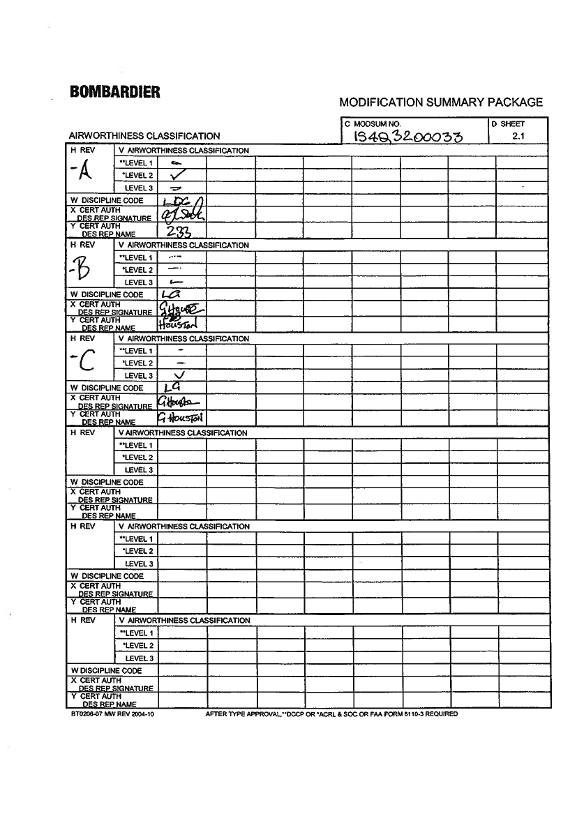
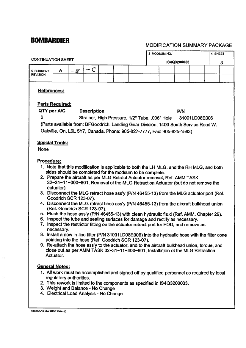
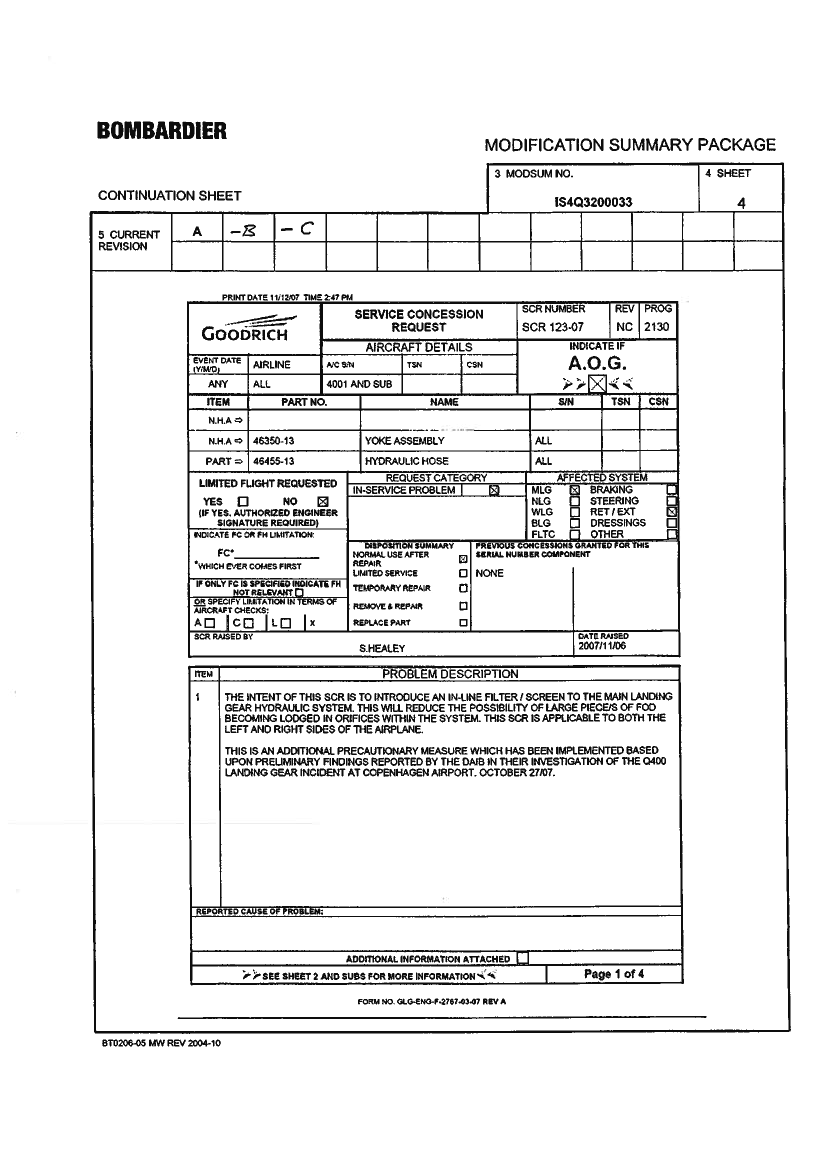
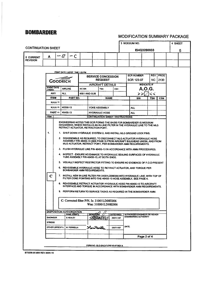
APPENDIXA FLIGHT HISTORY–TIMETABLE..................................................................................................... 63APPENDIXB ALTERNATELANDINGGEAREXTENSION CHECKLIST(PAGE14.1)................................................ 63EMERGENCYLANDING CHECKLIST(PAGE8.1 – 8.2) .......................................................................................... 63APPENDIXC AERODROME MAPEKCH ............................................................................................................. 63APPENDIXD RETRACTPORTRESTRICTOR EXAMINATION REPORT.................................................................... 63APPENDIXE SERVICEBULLETINNO. 84-32-54................................................................................................. 63APPENDIXF MODIFICATIONSUMMARYPACKAGENO. IS4Q3200033 .............................................................. 63
4
GLOSSARY OF ABBREVIATIONSAIBATDAIPATCATAACARSAMMATPLACCCA1CA2CASCVRUTCDLIDMEDNDOIDOMDOWEASAFARFDRFLFWDGVIGEOGPGPWSIPCIFRILSICAOJARLDGLAMLAWLMCLITOMAccident Investigation Board, DenmarkActual Time of DepartureAeronautical Information PublicationAir Traffic ControlAir Transport AssociationAircraft Communication Addressing and Reporting SystemAircraft Maintenance ManualAirline Transport Pilot's LicenseArea Control CentreCabin Attendant assigned to station no 1Cabin Attendant assigned to station no 2Calibrated Air SpeedCockpit Voice RecorderCoordinated Universal TimeDead Load IndexDistance Measurement EquipmentDownDry Operating IndexDry Operating MassDry Operating WeightEuropean Aviation Safety AgencyFederal Aviation RegulationFlight Data RecorderFlight LevelForwardGeneral Visual InspectionGeographicGlide PathGround Proximity Warning SystemIllustrated Parts CatalogInstrument Flight RulesInstrument Landing SystemInternational Civil Aviation OrganizationJoint Aviation RegulationLanding GearLanding MassLanding WeightLast Minute ChangeLoaded Index at Take-Off Mass5
LITOWLIZFMLIZFWMAGMLGMAC TOMMAC TOWMSLMSVMHzNASNTSBNLGPAXPAPSEUQRHRASTDSSVTOFTOMTOWTWRTCASTSBTIFUNDLDVORVFRWOWZFMZFW
Loaded Index at Take-Off WeightLoaded Index at Zero Fuel MassLoaded Index at Zero Fuel WeightMagneticMain Landing GearMean Aerodynamic Cord at Take-Off MassMean Aerodynamic Cord at Take-Off WeightMean Sea LevelMechanical Sequence ValveMegahertzNational Aerospace StandardNational Transportation Safety Board, USANose Landing GearPassengersPressure AltitudeProximity Switch Electronics UnitQuick Reference HandbookRadio AltimeterScheduled Time of DepartureSolenoid Sequence ValveTake-Off FuelTake-Off MassTake-Off WeightTowerTraffic Alert and Collision Avoidance SystemTransport Safety Board, CanadaTrip FuelUnder LoadVery High Frequency Omni Directional Radio RangeVisual Flight RulesWeight On WheelsZero Fuel MassZero Fuel Weight
6
FINAL REPORTHCLJ510-000449 AccidentAircraft:Engines:Crew:Place:Bombardier Aerospace Inc. A/C registration:DHC-8-4022 Pratt & Whitney PW150A Type of Flight:4 - No injuriesPassengers:Copenhagen AirportDate and time:Kastrup (EKCH) RWY 04RLN-RDIScheduled, IFR40 - No injuries27.10.2007 1453 UTC
All times in this report is UTC.The Area Control Centre at Copenhagen Airport, Kastrup (EKCH) notified the Accident InvestigationBoard, Denmark (AIB) on October 27th2007, at 1525 hrs.The Transportation Safety Board (TSB), Canada, Statens Havarikommisjon for Transport (SHT), Norway,the International Civil Aviation Organization (ICAO) and the European Aviation Safety Agency (EASA)were notified on October 27th2007. The TSB, Canada, had, in accordance with ICAO Annex 13 appointedan accredited representative for the investigation.SynopsisThe accident flight was a scheduled IFR flight from Bergen Flesland Airport (ENBR) in Norway toCopenhagen Airport Kastrup (EKCH) in Denmark.During the approach to EKCH, the flight crew was unable to fully extend the right Main Landing Gear(MLG).After a number of unsuccessful alternate extension attempts, the flight crew declared that the landingwould be an emergency landing. The MLG was stuck in an almost up position.The aircraft landed on runway 04R and came to rest on taxiway C area. The aircraft was evacuated within50 seconds and no one was injured.The accident occurred in daylight and under visual meteorological conditions (VMC).SummaryThe summary contains findings and factors that was established in the investigation.The Solenoid Sequence Valve (SSV) down port and up port filter elements may not withstand normalLanding Gear hydraulic operational pressure fluctuations and may collapse. At a given time prior to theaccident, the SSV down port filter element collapsed and the O-ring located adjacent to the filter elementmigrated into the hydraulic line.
7
The Mechanical Sequence Valve (MSV) was of such a design that it was impossible for the O-ring to passthrough the MSV on its way from the SSV down port to the MLG Retraction/Extension Actuator RetractPort Restrictor. However, the MSV was replaced on 22ndOctober 2007.The operator maintenance organization had only Nose Landing Gear (NLG) MSV’s on stock. Therefore,the MSV supplied from stock on 22ndOctober 2007 was a NLG MSV P/N 48303-7 S/N FAH-0345 havingReducers installed to fit the NLG.The information, as a unified whole given by both the aircraft manufacturer and the operator computerizeddata system was unclear, not easily seen through and misleading to the maintenance personnel; misleadingthe maintenance personnel to reconfigure the delivered Authorized Release Certificate approved NLGMSV P/N 48303-7 S/N FAH-0345 to fit the MLG MSV. There were no procedures available forreconfiguring the MSV.For that reason by a maintenance action, the rogue O-ring was transferred from the SSV side of thehydraulic line to the Actuator side of the hydraulic line while trapped inside a Union when the Unionsfrom the removed MSV Valve Body P/N 48303-103 S/N FAH-0107 were reused on the NLG MSV P/N48303-7 S/N FAH-0345 to fit the MLG.It was not observed that the O-ring was trapped inside one of the reused Unions. The circumstances werehuman factor related. A thorough inspection of the Unions according to a defined inspection proceduremight have led to a finding of the rogue O-ring, but the maintenance personnel had no proceduresavailable.The Main Landing Gear (MLG) Retraction/Extension Actuator had no protection (in-line filter) againsthydraulic fluid contamination.At a given time during retraction of the MLG, the O-ring was able to enter the Retract Port Restrictor ofthe Actuator. While trapped inside the restrictor, the O-ring was damaged and cut into several pieces.On the accident flight on 27thOctober 2007 during extension of the Landing Gear, the right MLGextension fluid flow had enough flow to force a part of the damaged O-ring through the small orifice holein the floating valve in the Retract Port Restrictor which blocked off the hydraulic fluid flow.The MLG Retraction/Extension Actuator was hydraulically locked by the blocked Retract Port Restrictor,which caused the right MLG to be stuck in the almost up position. In this situation, it was not possible toextend the right MLG.Safety recommendationsAs a result of the investigation of this accident, the Accident Investigation Board, Denmark made tworecommendations to the European Aviation Safety Agency (EASA).
8
1.Factual information1.1History of the flight(For more details see appendix A: Flight history – timetable)The aircraft departed Bergen, Flesland (ENBR) on the 27thOctober 2007. The planned destination wasCopenhagen Airport, Kastrup (EKCH). The flight crew contacted Copenhagen Approach (119,800 MHz)and was informed that they could expect an ILS approach to runway 04L. At first contact with KastrupTower (119,350 MHz) the flight was cleared to land on runway 04R.While the aircraft was descending through 1245 ft Radio Altimeter (RA), the Landing Gear was selecteddown. The Landing Gear indication was: Nose Landing Gear (NLG) down and locked, left Main LandingGear (MLG) down and locked and right MLG in Transit. A go around was initiated.A few seconds later, the Landing Gear was selected up and the Landing Gear was up. The Landing Gearup indication was normal. Kastrup Tower was informed about the Landing Gear problem and that theaircraft was making a go around. The flight crew was instructed to contact Copenhagen Approach on thefrequency 118.450 MHz.Copenhagen Approach was informed that the aircraft was going around due to a Landing Gear problem. Inorder to solve the Landing Gear problem, the flight crew requested radar vectors around the area.The Landing Gear was selected down at 1351:11 hrs and the Landing Gear indication was: NLG down andlocked, left MLG down and locked and right MLG in Transit.The commander made radio contact with the operator technical department. He explained that the rightMLG would not extend. The commander asked if he should use the Alternate Landing Gear Extensionprocedure. A decision was made to use the Alternate Landing Gear Extension procedure. The commanderwent through different Landing Gear procedures using the Quick Reference Handbook (QRH) trying tofind the appropriate procedure. The commander found the Alternate Landing Gear Extension procedureand followed the procedure using the QRH. Without success, the commander manually tried to pump theLanding Gear down.The cabin crew was informed that they should expect an Emergency Landing in about 20 to 25 minutes.The operator technical department was informed that the Alternate Landing Gear Extension procedure wasunsuccessful and that the right MLG was now in the up position.The commander made a passenger briefing explaining that the landing would be an Emergency Landingand that the landing was expected in about half an hour.
9
Copenhagen Approach instructed the first officer to contact Kastrup Final on the frequency 119.100 MHz.The first officer made radio contact with Kastrup Final and was informed that the flight was the only flighton the frequency.The flight crew went through the tasks and procedures before the Emergency Landing. The cabin crewinformed the commander that the Emergency Landing briefing was completed.Once more, the flight crew tried to pump the Landing Gear down. At this time, they were concerned aboutthe remaining amount of fuel.Kastrup Final (119.100 MHz) was informed that the aircraft was ready for the approach.The flight crew made an approach briefing and completed the Approach Checklist.The flight crew decided to shut down the right engine. The right Engine Condition Lever was set to FuelOff. At the same time, the warning horn started to sound.Kastrup Final cleared the aircraft to land and informed the crew that the wind was from 100 degree at 3knots. The commander informed Kastrup Final that the right engine had been shutdown.When flaps 15� were set, the Landing Gear Warning started to sound. Trough the remaining flight, thewarning continued.While the aircraft was passing through approximately 800 feet RA, the commander instructed thepassengers to brace for impact. Thereafter and until the aircraft came to a full stop, the cabin attendantsrepeated the command to brace for impact.The Ground Proximity Warning System (GPWS) started issuing warnings “TooLow Gear”when theaircraft passed 531 feet RA. During the remaining flight, the GPWS continued issuing warnings withshorter and shorter intervals.Abeam taxiway B3, the aircraft left MLG touched down on runway 04R. After touch-down, the leftEngine was selected to reverse and the power was increased. The aircraft followed the runway centrelinein approximately 20 seconds. The aircraft right propeller, aft fuselage and right wingtip made contact withthe runway surface. The aircraft started to turn to the right and as it departed the runway it damaged tworunway edge lights.The aircraft came to rest on taxiway C area heading southeast 120�.
10
1.2Injuries to personsInjuriesCrewFatal-Serious-Minor/None41.3Damage to aircraftThe aircraft was substantially damaged.
Passengers--40
Others---
1.4Other damageThe runway surface was found to have several scratch marks from the aircraft tail section, right wing tip,right propeller and the nose landing gear. When the aircraft departed the runway 04R to the right intotaxiway C area, the aircraft hit two runway lights.1.5Personnel informationThe commander:Male, 48 years.Certificate:Airline Transport Pilot License (ATPL).Medical:Class 1, Valid.Flying experience:All typesDHC-8LandingsFirst officer:Certificate:Medical:Flying experienceaccording to theoperator:All typesDHC-8Last 24 hrs6:01 hrs6:01 hrs2Last 90 days86:53 hrs86:53 hrs37Total11.156 hrs2.876:23 hrs990
Male, 46 years.Airline Transport Pilot License (ATPL).Class 1, Valid.Last 24 hrsLast 6 monthsTotal
3:55 hrs3:55 hrs
267 hrs267 hrs
8.135 hrs-
11
1.6Aircraft information1.6.1General aircraft informationThe aircraft was a twin engine DHC-8-402 (Q400) manufactured by Bombardier Aerospace Inc.Year of manufacture:Serial number:Registration:Certificate of airworthiness:Engines:Propeller:MTOW:Aircraft total flight hours:Aircraft cycles:Maintenance:The last Line-check:The last “A” inspection:20004024Registered in Norway as LN-RDI on 1stJuly 2003Issued by the Civil Aviation Authority Norway (CAAN) on 6thSeptember 2007 was valid until 30thSeptember 20082 ea Pratt & Whitney PW150A2 ea Dowty Aerospace R408/6-123-F/1728.998 kg12.071,3614.967The aircraft maintenance records were verified to be in compliance withthe established maintenance programWas accomplished on 12thOctober 2007Was accomplished on 1stSeptember 2007
1.6.2Right Main Landing Gear parts replaced October 2007.The following Right Main Landing Gear system parts were replaced in the period from the 16thOctober2007 to the 24thOctober 2007 in connection with trouble shooting:Part removed: Date: 16.10.2007Solenoid Sequence ValveP/N: 48302-3S/N: FAH-0083Part removed: Date: 21.10.2007Door ActuatorP/N: 46830-5S/N: MAL-0307Part removed: Date: 22.10.2007Mechanical Sequence ValveP/N: 48303-5S/N: FAH-0107Part removed: Date: 24.10.2007MLG Retraction/Extension ActuatorP/N: 46550-9S/N: MAL-0117Part installed: Date: 16.10.2007Solenoid Sequence ValveP/N: 48302-3S/N: FAH-0200Part installed: Date: 21.10.2007Door ActuatorP/N: 46830-5S/N: MAL-0095Part installed: Date: 22.10.2007Mechanical Sequence ValveP/N: 48303-7S/N: FAH-0345Part installed: Date: 24.10.2007MLG Retraction/Extension ActuatorP/N: 46550-9S/N: MAL-007412
1.6.3Mass and Centre of Gravity (extract from Load Sheet Final)The aircraft version: 76 passengers.BGODOW dry operating weight (kg):ZFW zero fuel weight (kg):TOF take-off fuel (kg):TOW take-off weight (kg):TIF trip fuel (kg):LAW landing weight (kg):UNDLD under load (kg):PAX M passengers:DOI dry operating index:DLI dead load index:LIZFW loaded index at zfw:LITOW loaded index at tow:MAC TOW mean aerodynamic cord at tow:BALANCE LIMITS BEFORE LMCFWD / AFT:12 / 3210 / 32AT ZFWAT TOWCPH18.530 kg22.343 kg2.900 kg25.243 kg1.500 kg23.743 kg3.755 kg38/0/22029272730TTL38/0/2MAX28.009 kgMAX28.998 kgMAX26.308 kgLN-RDICrew 2/2
The aircraft was within the mass and balance limitations. The estimated mass of the aircraft at the time ofthe accident was approximately 23.143 kg (ZFW plus 800 kg fuel).1.6.4Landing Gear system information1.6.4.1General descriptionThe tricycle gear is a retractable dual wheel installation. The Right and Left Main Landing Gear (MLG)retract aft into the nacelles and the Nose Landing Gear (NLG) retracts forward into the nose section. Geardoors completely enclose the Landing Gear when it is retracted and partially enclose the gear when it isextended.The cockpit advisory lights show the position of gear doors and down-locks. An audible warning sounds ifthe gear is not extended and the aircraft is in a landing configuration.A Proximity Switch Electronics Unit (PSEU) monitors and controls the operation of the Landing Gearcomponents.An alternate Landing Gear extension method can be used to extend the gear if the primary extensionmethod fails. There is also an alternate down-lock verification system.Landing Gear operation is controlled and monitored from the Landing Gear Control Panel, adjacent to theEngine Display in the cockpit. The Landing Gear is selected up or down by moving the Landing Gear13
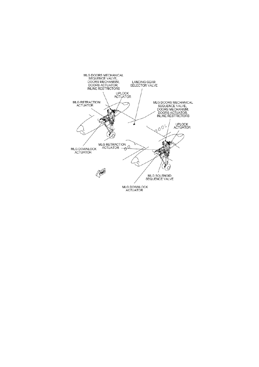
Selector Lever. A Lock Release selector lever must be held down to let the gear selector lever move ineither direction. An alternate down-lock verification system confirms down-lock engagement if theprimary down-lock indication is in doubt. Three green down-lock verification lights are located under theLanding Gear Alternate Extension door in the cockpit floor.MLG and the location of the components are shown on the following drawing.
1.6.4.2Main Landing Gear retractionHydraulic pressure is supplied to each MLG down-lock release actuator to release the down-lock.Hydraulic pressure is supplied through an energized Solenoid Sequence Valve (SSV) to the open side ofthe MLG aft door actuators. This causes the MLG aft doors to open. The operation of the down-lockrelease actuator and the MLG aft door actuators are monitored by the PSEU. The MLG door mechanismoperates a Mechanical Sequence Valve (MSV) to interlock the retraction/extension part of the hydraulicsystem. This continues until the doors are wide enough open for the Landing Gear to retract so that it doesnot touch the doors. At approximately 93 percent travel of the MLG aft door, the MLG aft door linkageactivates the MSV. When the MSV has been activated, hydraulic pressure is supplied to the up side of theMLG Retraction /Extension Actuator. The MLG starts to travel to the fully retracted position where it islocked in place by the mechanical up-lock hook. The proximity sensors monitor the gear and doorpositions.When the PSEU receives the input signals that the MLG is up and locked, the PSEU de-energizes theSSV. This causes the SSV to supply pressure to the close side of the MLG door actuators and close thedoors. At approximately 7 percent reverse travel of the MLG doors, the MSV’s stop their operation. Thisaction removes hydraulic flow from the up side of the MLG Retraction/Extension Actuators. Inlinerestrictors bypass the MSV and keep the MLG Retraction/Extension Actuators pressurized to 3000 psi.
14
Pressure is kept at 3000 psi until the Landing Gear hydraulic system is depressurized upon completion ofthe retraction cycle.1.6.4.3Main Landing Gear extensionWhen the Landing Gear selector lever is moved to the DN position, the SSV remain de-energized. The de-energized SSV supply hydraulic pressure to the open side of the MLG aft doors actuators to open theMLG aft doors. At approximately 93 percent travel of the MLG aft door, the MLG aft door linkageactivates the MSV. The valve supplies hydraulic pressure to the up-lock release actuators and to the downside of the MLG Retraction/Extension Actuators. The in-line restrictors slow hydraulic flow to, andpressure built up in the MLG Retraction/Extension Actuator and the up-lock release actuator, until thedoors reach the 93 % open position at which point the activation of the MSV ports full flow to the twoactuators.The MLG starts to travel to the down and locked position. There are four proximity sensors used tomonitor the MLG extension sequence. Each MLG has two down and locked sensors and one MLG aftdoor closed sensor. When the PSEU receives input signals that the MLG is down and locked, the PSEUenergizes the SSV. Pressure is supplied to the MLG aft door actuators to close the MLG aft doors. Atapproximately 7 percent reverse travel of the MLG doors, the MSV’s stop their operation. This actionremoves hydraulic flow from the up side of the MLG Retraction/Extension Actuators. Inline restrictorskeep the MLG Retraction/Extension Actuators pressurized to 3000 psi at the end of the extensionsequence.The advisory light sequence during extension starts with the LEFT, NOSE, and RIGHT red unsafe lightsand the amber gear selector handle light coming on. Then the amber door advisory lights illuminate toindicate the hydraulically operated gear doors are open. When the MLG is fully extended the over centrelock links are brought into lock by springs. The actuator maintains them in that position.When the Landing Gear is locked in the down position, the red unsafe lights and the selector handle lightgo out. Then the green LEFT, NOSE, and RIGHT advisory lights come on. Finally, the gear door advisorylights go out when the hydraulically operated doors are closed.The solenoid selector valve stays powered to allow for continued hydraulic pressure acting on the gearwhen down and locked, but primary down-lock is by the over-centre locks.1.6.4.4Landing Gear alternate extensionThe Landing Gear extension Inhibit switch is installed in the cockpit ceiling, adjacent to the Main LandingGear alternate release door. The switch sends a signal to the PSEU to remove power from the LandingGear selector valve and the door SSVs. Additionally, the PSEU will bring on the LG INOP caution light.When the main Landing Gear alternate release door on the cockpit ceiling is opened it mechanically opensa bypass valve in the normal hydraulic extension system, porting the UP and DN lines to return and givesaccess to the MLG release handle. Pulling the handle releases the MLG doors and up-lock hooks. Themain gear will free fall but may not fully lock.
15
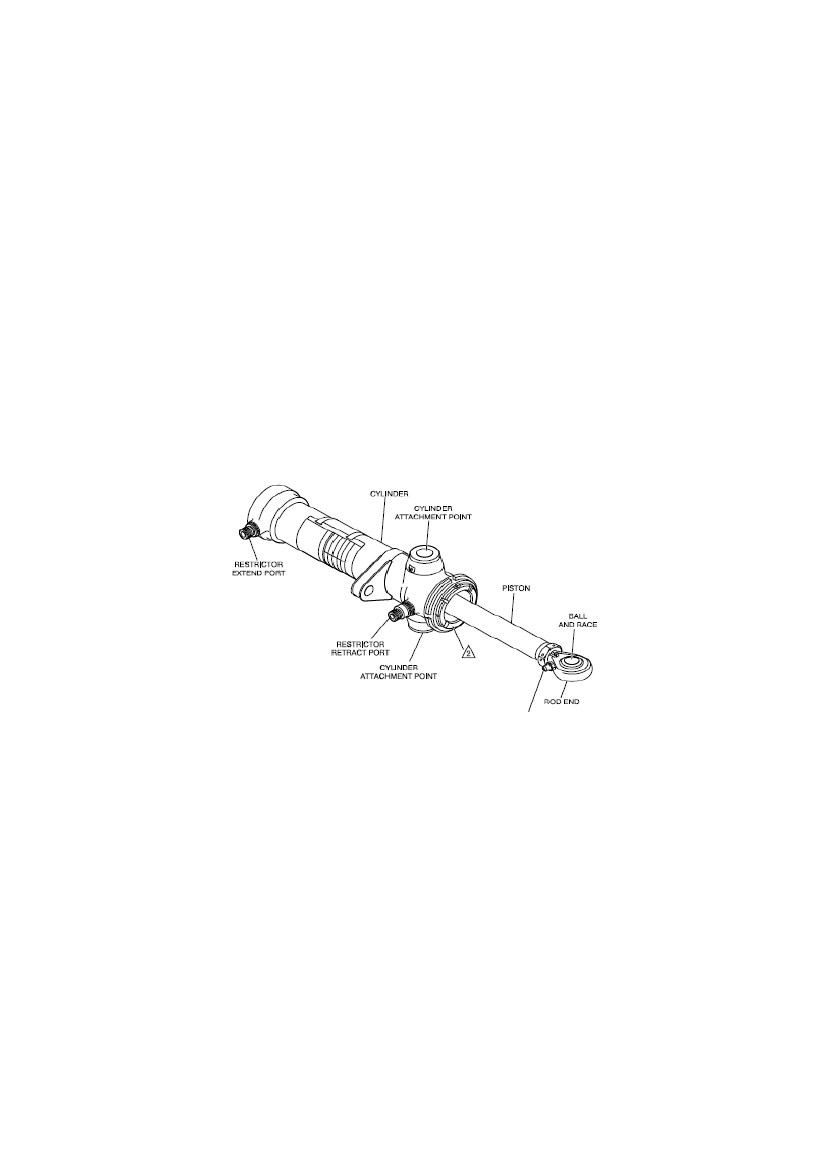
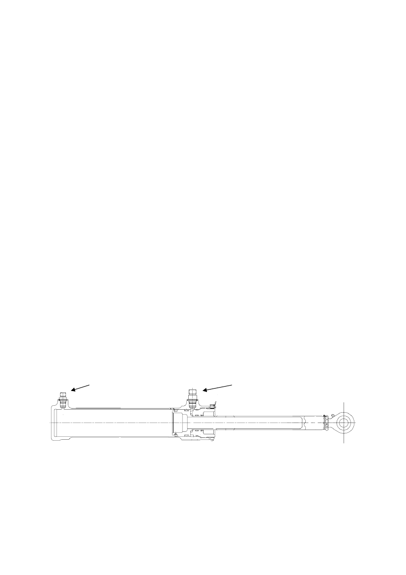
The Landing Gear alternate extension door, on the cockpit floor, must then be fully opened giving accessto the alternate extension hand-pump and the NLG release handle. Opening the door mechanicallyoperates the MLG alternate selector valve. If the MLG does not reach the down and locked position, theextension pump handle, located behind the right pilot seat, is inserted into the pump handle socket andoperated to complete main gear extension and subsequent down-lock. Both the Landing Gear alternateextension door and the MLG alternate release door must be left fully open after alternate Landing Gearextension. When the NLG release handle is pulled, the nose gear up-lock and doors are released and thenose gear free falls to a down and locked position, assisted by the airflow.1.6.4.5Main Landing Gear Retraction/Extension ActuatorThe MLG Retraction/Extension Actuator, shown on the following drawing, is a hydraulic device that hastwo ports. There are restrictors in both retract and extend ports. The rod end of the actuator piston has aspherical rod-end with a lubrication fitting. The MLG Retraction/Extension Actuator cylinder is attachedto the lower front of the MLG yoke cross beam. The rod end is attached to the centre top of the MLGshock strut.
MLG Retraction/Extension Actuator.
16
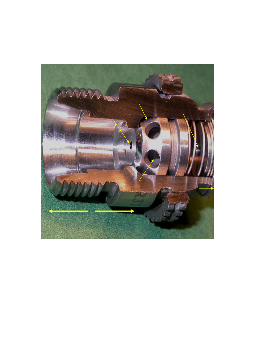
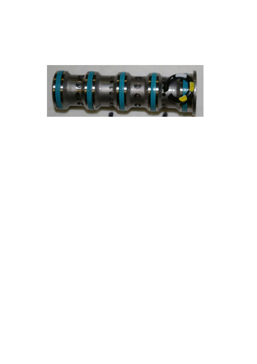
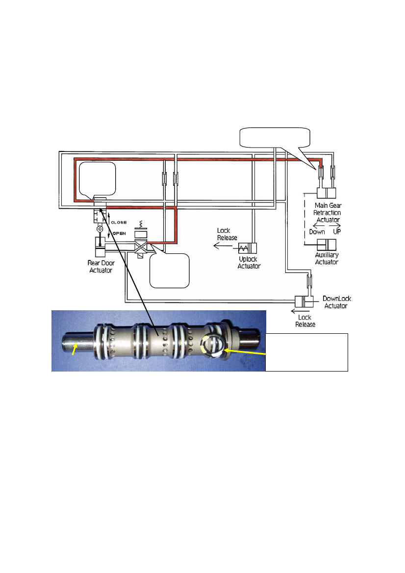
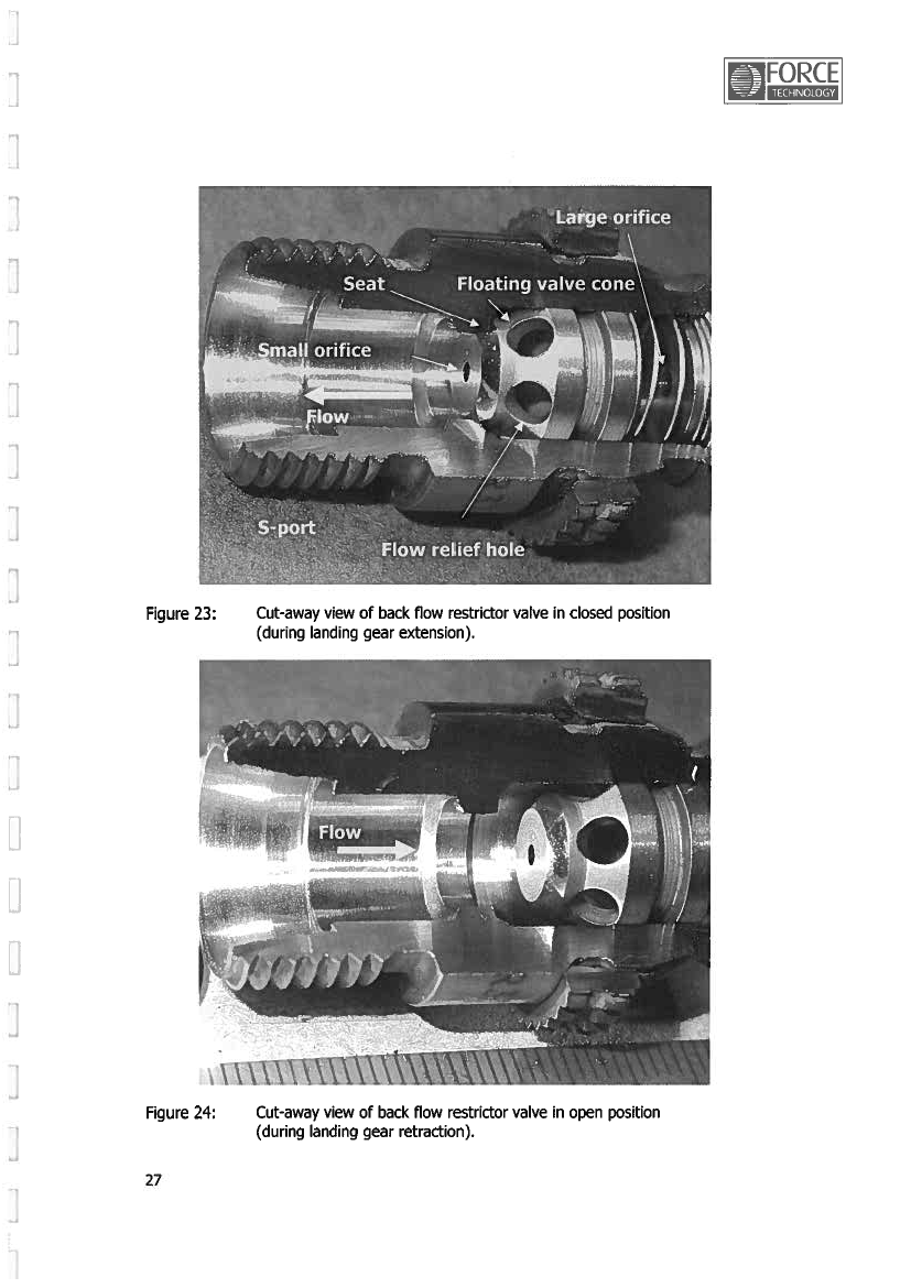
The Retraction/Extension Actuator acts as a damper through the restrictor in the retract port, when the gearis moving to the down position.The Retract Port Restrictor, shown on the following picture in a cut away view, allows a larger volume ofhydraulic fluid to pass when the gear is retracting (Floating Valve open) and less fluid when the gear isextending (Floating Valve closed).
Floating valveLarge orificeSmall orifice
Retract port
Flow relief hole
Actuator
Extend flow direction
Retract flow direction
17
1.6.4.6Landing Gear down operationThe Landing Gear system is powered by the No. 2 hydraulic system.Selecting gear down the PSEU will energize Solenoid A and re-position the Landing Gear Selector Valveand provide pressure to the down side of the actuators (shown on the following figure).Pressure =blue.Return =green.
The figure below shows the system before all the doors and gears start to move. The restrictors slow thereturn flow from the actuators to allow time for the doors to fully open. Once the MSVs open the systemhas an un-restricted return path. The Retraction/Extension Actuator acts as a damper through the restrictorin the retract port, when the gear is moving to the down position (shown on the following figure).
18
Once the PSEU register the gear is down and locked it Energizes the SSVs and the doors close and theDownlock Actuator engages (shown on the following figure).
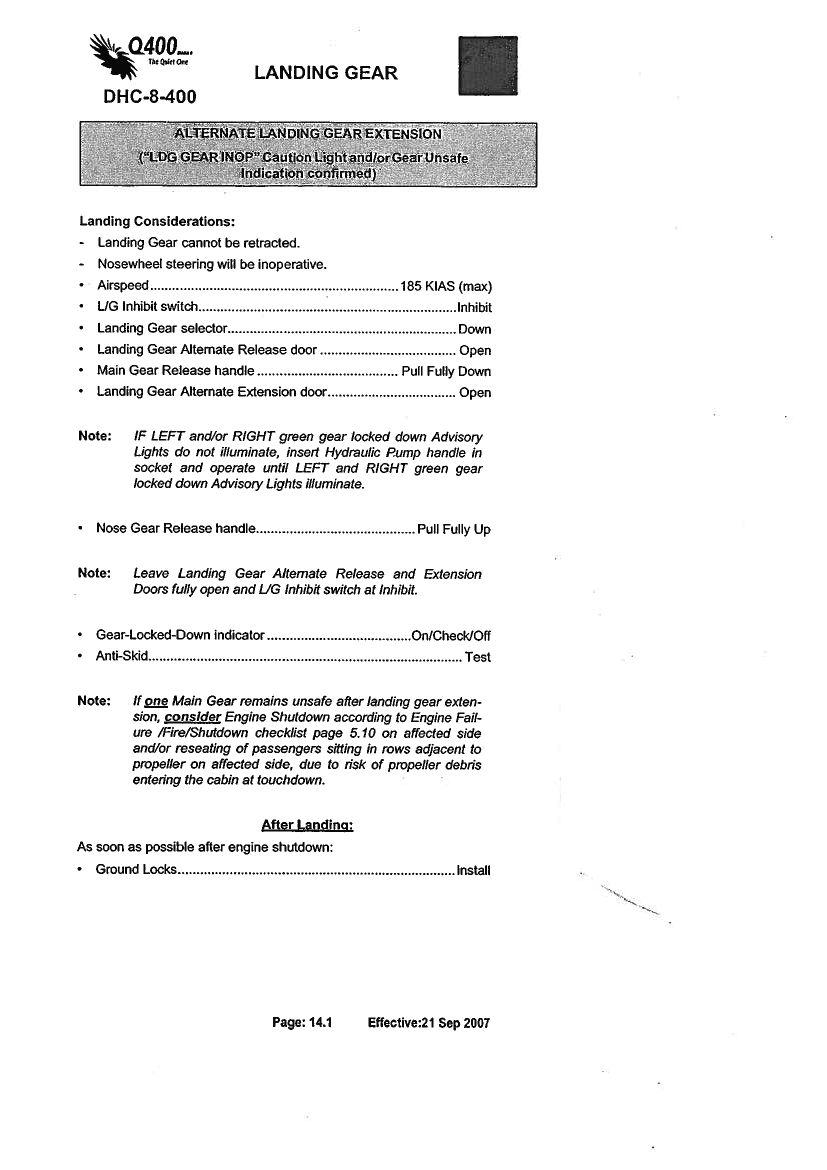
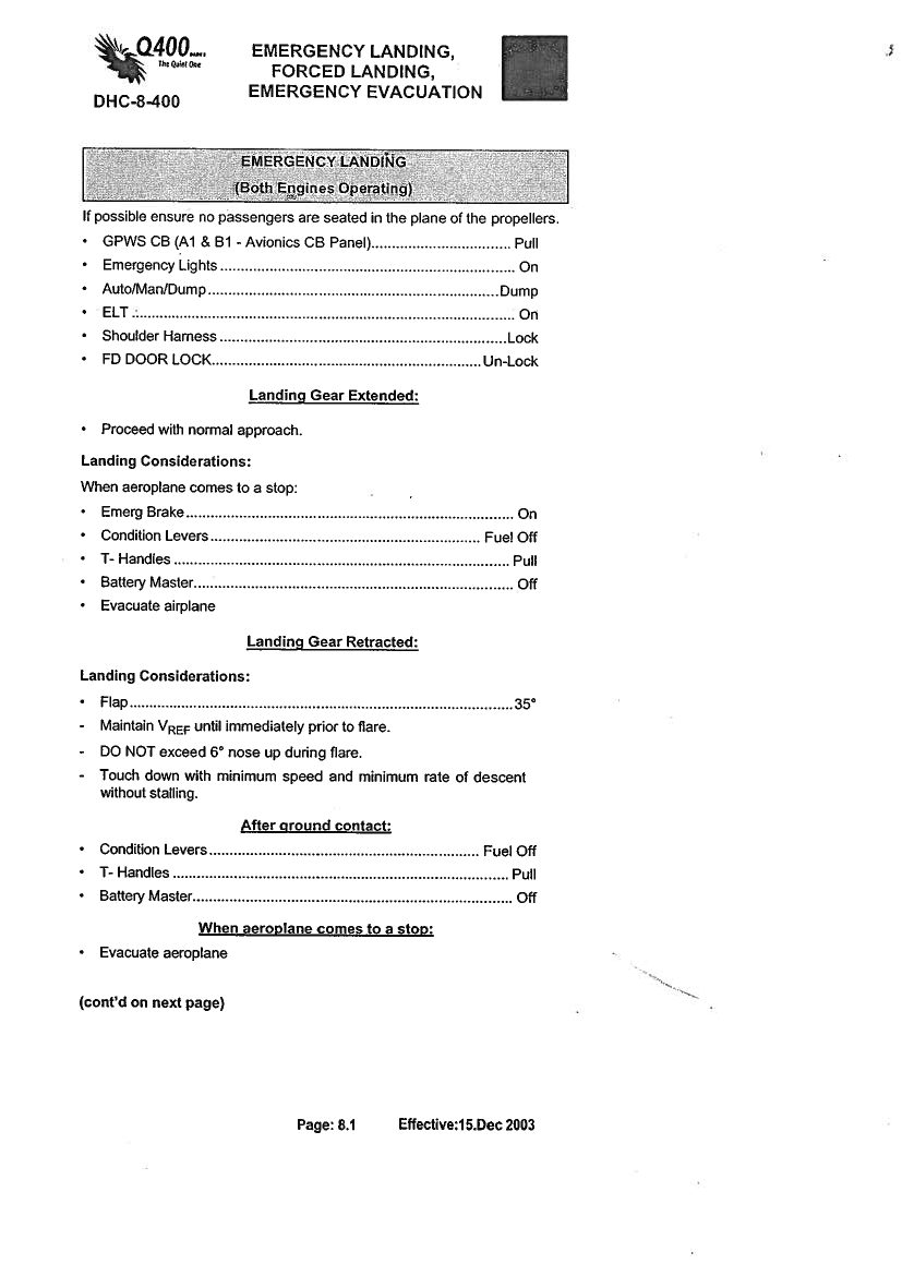
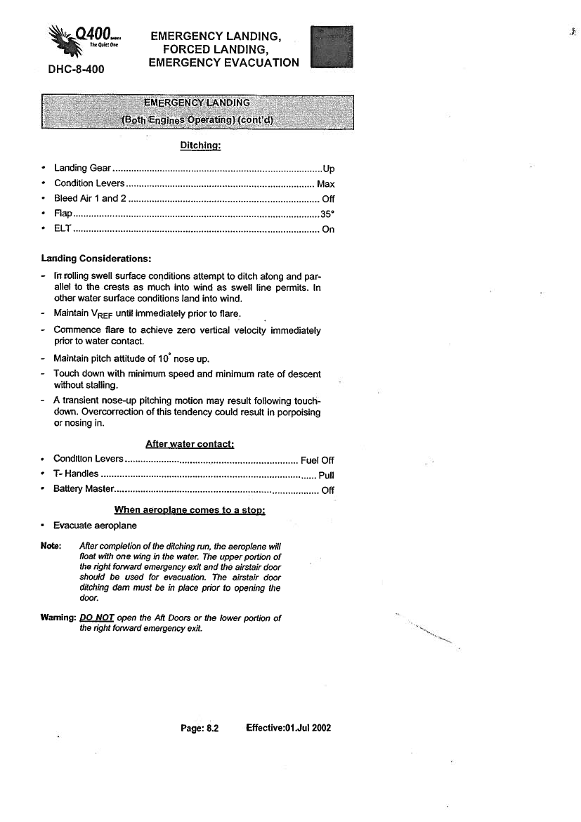
1.6.4.7Warning systemsThe warning system (horns) will be activated in situations where a power lever is retarded to a certainposition or flaps are selected but the Landing Gear is not down and locked.The Ground Proximity Warning System (GPWS) will be activated when the aircraft descends below acertain altitude if the Landing Gear is not down and locked.1.6.5Quick Reference Handbook (QRH).The Alternate Landing Gear Extension checklist (page 14.1 of the QRH) and the Emergency Landingchecklist (page 8.1 – 8.2 of the QRH) are enclosed as appendix B.The above mentioned QRH are based on the aircraft manufacturers QRH as required by the authorities.As a result of two other DHC-8 aircraft accidents in the year of 2007 caused by Landing Gear collapse, theAlternate Landing Gear Extension checklist in the QRH was revised.The following note was added to the QRH:“IfoneMain Gear remains unsafe after Alternate Landing Gear Extension,considerEngine Shutdownaccording to Engine Failure/Fire/Shutdown checklist page 5.10 on affected side and/or reseating ofpassengers sitting in rows adjacent to the propeller on affected side, due to risk of propeller debrisentering the cabin at touchdown.”With reference to Chapter 1.1 History of the flight and Appendix A Flight history – timetable based on theCVR and FDR data:Without success, the flight crew followed the Alternate Landing Gear Extension checklist.19
The right MLG remained in an almost up position which changed the conditions into a situation where theEmergency Landing checklist would have been the one to follow.The Emergency Landing checklist was not performed or not adequately performed. The first item on thechecklist was “Pullthe GPWS CB (A1 & B1 – Avionics CB Panel)”.Because the CB’s was not pulled, theflight crew was disturbed by the GPWS warning horns during the remaining flight.The Alternate Landing Gear Extension checklist did not contain information/references to the EmergencyLanding, Forced Landing Emergency Evacuation checklist in a situation where the use of this checklist didnot solve a Landing Gear unsafe problem.It must be added that there are no certification requirements for checklists (manufacturers and/oroperators) to refer to other relevant checklists.The above mentioned issues were also issues in the AIB investigation on the DHC-8 accident at AalborgAirport on September 9th2007 (report HCLJ510-000433).In the Aalborg accident, the flight crew found that the QRH was not helpful. Twice without success, theyused the Alternate Landing Gear checklist. The crew was going to do an emergency landing and theEmergency Landing checklist was the one to follow. This checklist was not used which caused disturbance(GPWS warning horns) of the flight crew during the remaining flight.1.7Meteorological informationThe TAF and METAR reports from October 27th2007 around the time of the accident at EKCH:271100 TAF-FC271400 TAF-FCekch 271140z 271221 08003kt 6000 few008 sct020 becmg 1618 4000 brbecmg 1820 22003kt prob30 1821 0300 bcfg=ekch 271440z 271524 vrb03kt 8000 few008 sct020 becmg 1618 4000 brtempo 1820 2000 prob40 2024 0300 bcfg=ekch 271420z 07002kt 8000 few013 bkn035 11/08 q1026 tempo 6000=ekch 271450z 09003kt 8000 ovc034 10/08 q1026 tempo 6000=ekch 271520z 11003kt 8000 few014 bkn033 10/08 q1026 tempo 6000=
271420 METAR271450 METAR271520 METAR
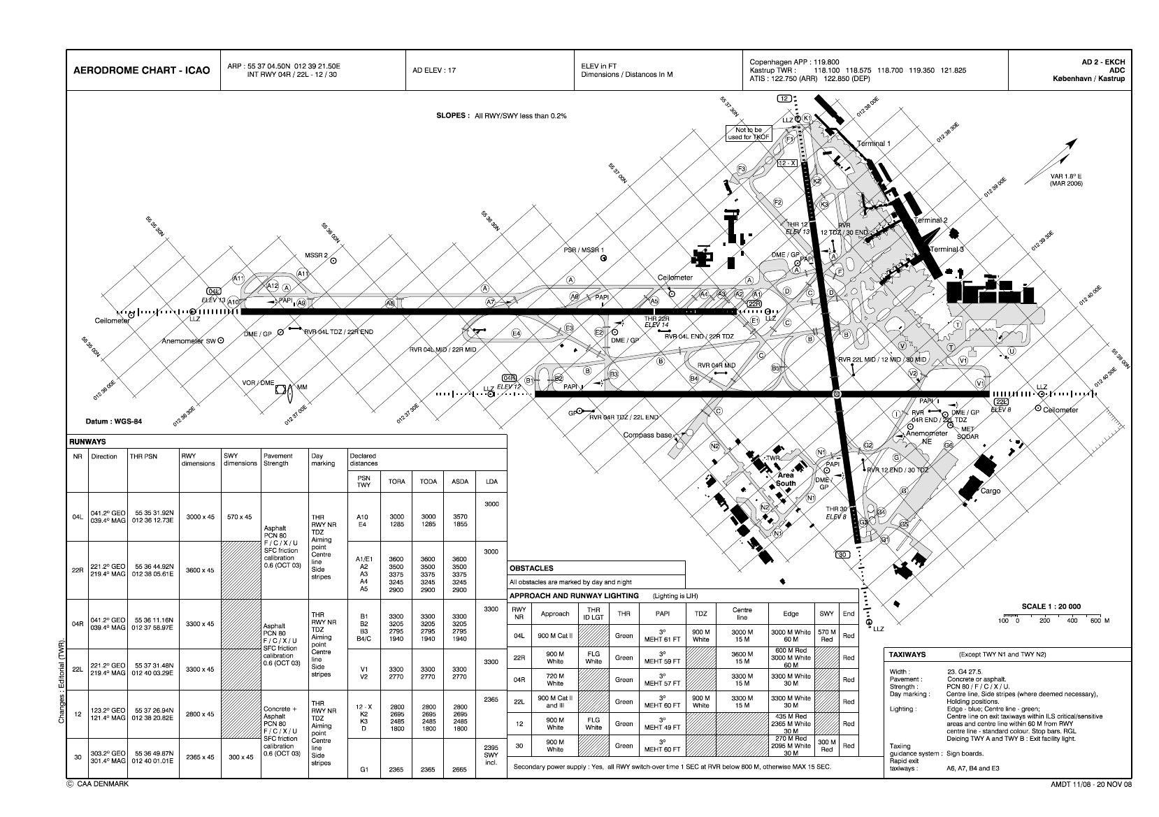
1.8Aids to navigationAt the time of the accident, Copenhagen Airport, Kastrup had the following radio navigation and landingaids for runway 04R: ILS/DME category I, VOR/DME, Approach and Runway lighting system, PAPI-L(3.0�), and ATC radar approach control.At the time of the accident, all navigation aids were functioning without remarks.
20
1.9CommunicationsThe flight crew was in radio contact with following ATC units: Kastrup Tower (119.350 MHz),Copenhagen Approach (118.450 MHz) and Kastrup Final (119.100 MHz). The flight crew was in radiocontact with ATC using the normal routine frequencies until 14:20:09 hrs. At that time, the flight wasassigned its unique controller, Final (119.100 MHz). The flight remained on that frequency (119.100MHz) through the remaining flight.The communication between ATC and the flight crew was recorded and was used in the investigation.1.10Aerodrome informationName:Copenhagen Airport, KastrupLocation indicator:EKCH.Position:4.4 nm southeast of Copenhagen (55 37 04.50N / 012 39 21.50E).Traffic permitted:IFR / VFR.Fire fighting and rescue:Approved to category 9 (ICAO Annex 14) and rescue boats.Runway 04R:Asphalt, dimensions 3.300 x 45 m, elevation 12 ft.Taxiway C south:South of runway 04R, concrete/asphalt total width 60 m.The approach and landing was performed on runway 04R. The runway 04R was selected for the landingby ATC because the runway was the most suitable for these kinds of operations. The runway 04R did nothave crossing road tunnels and the runway had many access taxiways and roads.Airport map from the Aeronautical Information Publication (AIP) Denmark is enclosed as appendix C.1.11Flight recorders1.11.1Cockpit Voice Recorder (CVR)The aircraft was equipped with a Honywell CVR, type SSCVR part number 980-6022-011 serial number0847. On the day of the accident, the CVR was removed from the aircraft. The data from the CVR was ofgood quality and was used in the investigation.1.11.2Flight Data Recorder (FDR)The aircraft was equipped with a Honywell FDR, type SSFDR part number 980-4700-027 serial number3691. On the day of the accident, the FDR was removed from the aircraft. The time reference used in theFDR was a cockpit clock (the commander). The time reference used by the FDR was 59 seconds ahead ofUTC. The data from the FDR was of good quality and was used in the investigation.
21
1.12Wreckage and impact information1.12.1GeneralAfter touchdown, the aircraft rolled 7 seconds before the right propeller and the aft part of the fuselagemade contact with the runway surface. 15 seconds after touchdown, the right wingtip made contact withthe runway surface. 27 seconds after touchdown, the aircraft came to rest on taxiway C area headingsoutheast 115�.
Before landing, the right engine was shut down. Four propeller blades were damaged as a result of groundcontact. The aft lower fuselage was damaged while skidding on the runway asphalt. The NLG right tiredeflated and the NLG was damaged when the aircraft side slipped into taxiway C. The right outer wingsustained minor damage while skidding on the runway asphalt and concrete. The fuselage surrounding thecabin area was undamaged.22
1.12.2Aircraft recovery and initial Main Landing Gear examinationAir bags were used to lift up the right wing and the wing was then supported by a jack.The MLG was found released from the up-lock hook but stuck in a position approximately 10 cm downfrom the hook.
MLG position in the right MLG wheel well
MLG up-lock hook found releasedMLG up-lock roller position in relation to theup-lock hookIt was not possible by manpower to move the MLG up or down from its stuck position. The MLG and thecomponents installed in the MLG wheel well were inspected and no abnormalities were found that couldexplain the stuck MLG. The Retraction/Extension Actuator was intact. One by one, the hydraulic hoseswere removed from the Retraction/Extension Actuator. The MLG stayed in the stuck position. Hydraulicfluid samples were obtained from the hoses that were connected to the actuator. No visible contaminationof the hydraulic fluid was observed.When the actuator was dismantled from the MLG yoke cross beam the MLG moved downwards. Theactuator was removed from the MLG, the restrictor ports were capped and the gear was fully lowered andlocked in the down position.The aircraft was towed away from taxiway C and placed in a hangar at the airport.
23
1.12.3Landing Gear function testsA Retraction/Extension Actuator serial number MAL-0062 was removed from another DHC-8 aircraft andinstalled on the right MLG for testing purposes. A hydraulic test unit was connected to the No. 2 hydraulicsystem.With focus on the right MLG, a number of hydraulic test cycles of the Landing Gear were performed:1) 6 normal cycles of retractions/extensions2) 2 alternate extensions3) 10 normal cycles of retractions/extensions4) 1 alternate extension5) 10 normal cycles of retractions/extensions6) 1 alternate extension7) 5 normal cycles of retractions/extensionsThe function of the Landing Gear system was found to be normal.The hydraulic pressure, return and pump case drain filters were removed and for the purpose ofexamination in a laboratory environment, hydraulic fluid samples were obtained from No. 2 hydraulicsystem.The color of the hydraulic fluid was darker than normal but no abnormal contaminations were found in thefilters or in the fluid samples. The fluid was compared to a reference sample of unused fluid specified forthe aircraft. There were no indications that the fluid was not identical to the reference sample.1.12.4Main Landing Gear Retraction/Extension Actuator examinationActuator data:Part number (P/N):46550-9Serial number (S/N):MAL-0074The actuator was repaired by an approved overhaul facility. The cylinder, piston, gland nut, rod end andrestrictors were replaced. An authorized release certificate EASA Form 1 was issued on 12thOctober 2007.The actuator was installed on the aircraft on 24thOctober 2007.
Extend port restrictor
Retract port restrictor
MLG Retraction/Extension Actuator
24
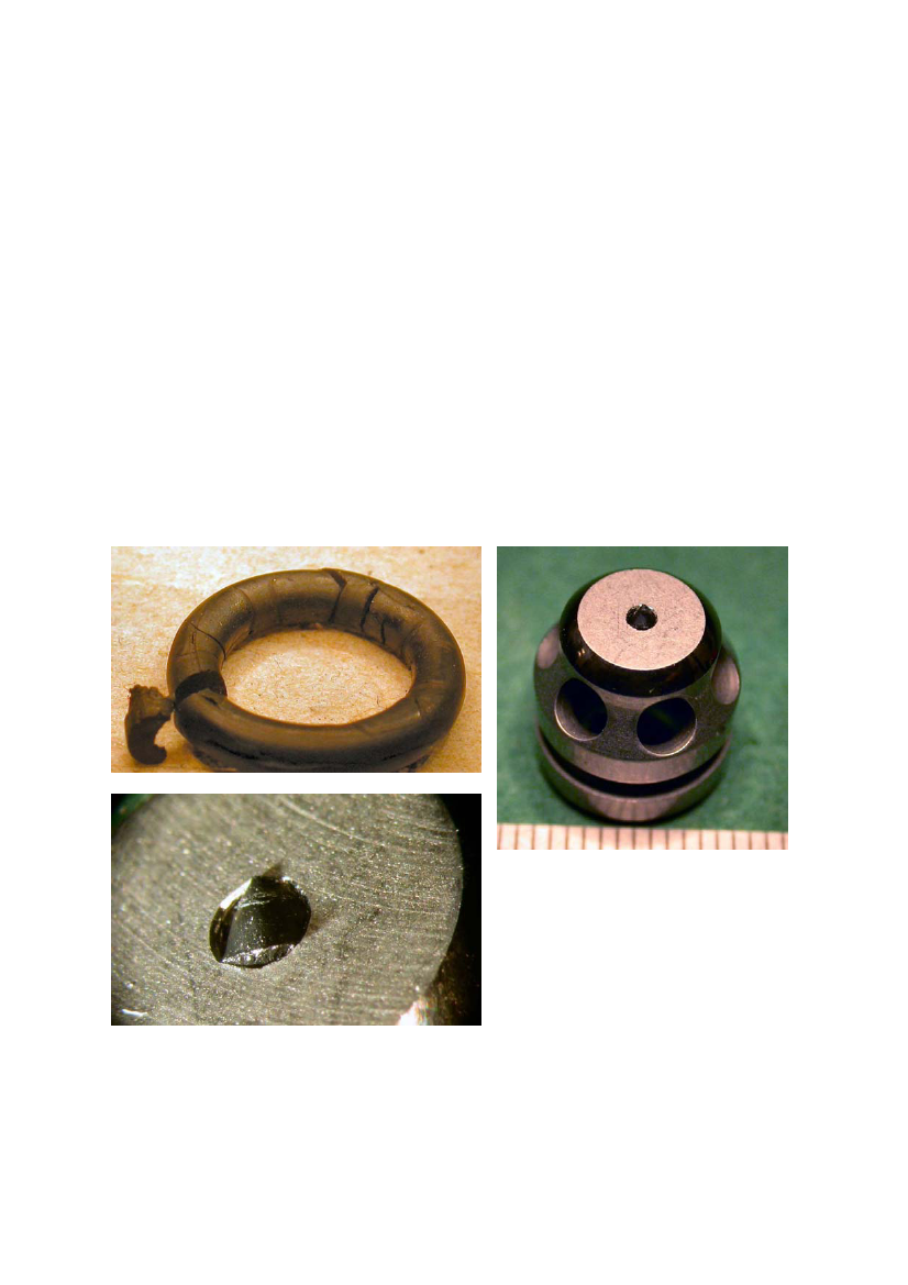
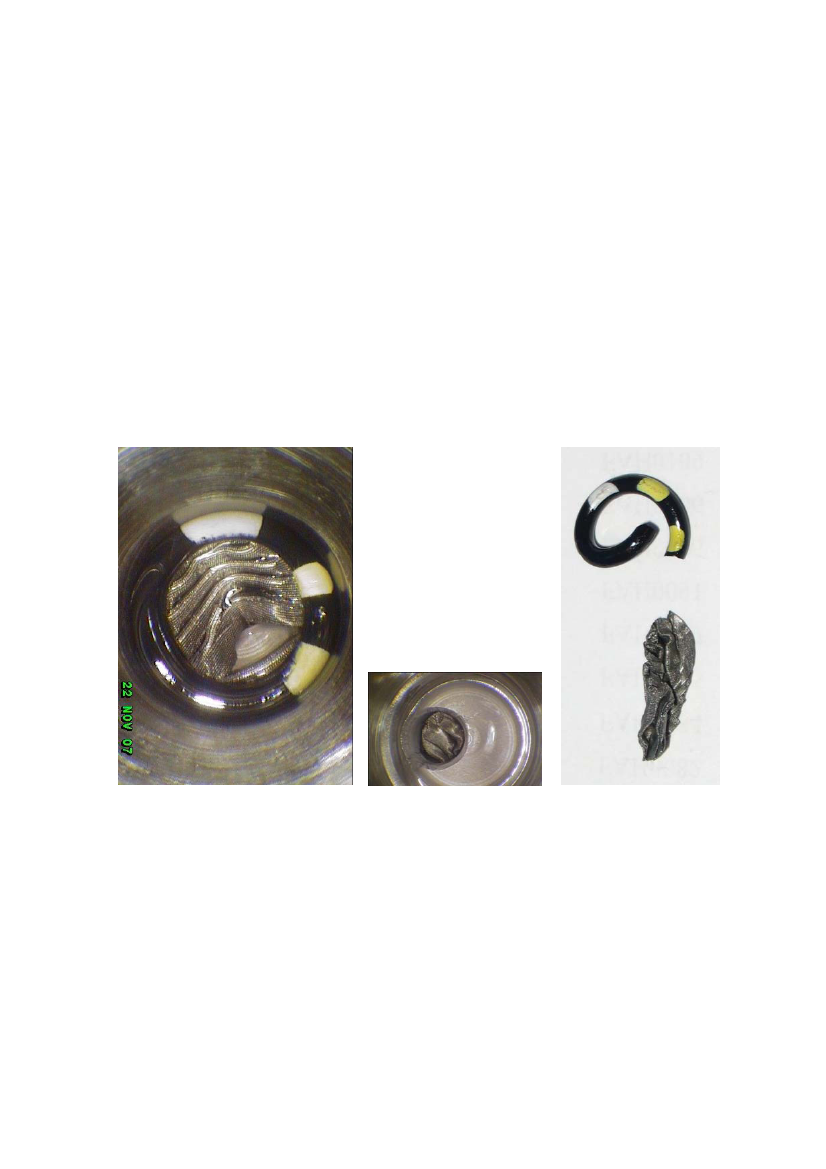
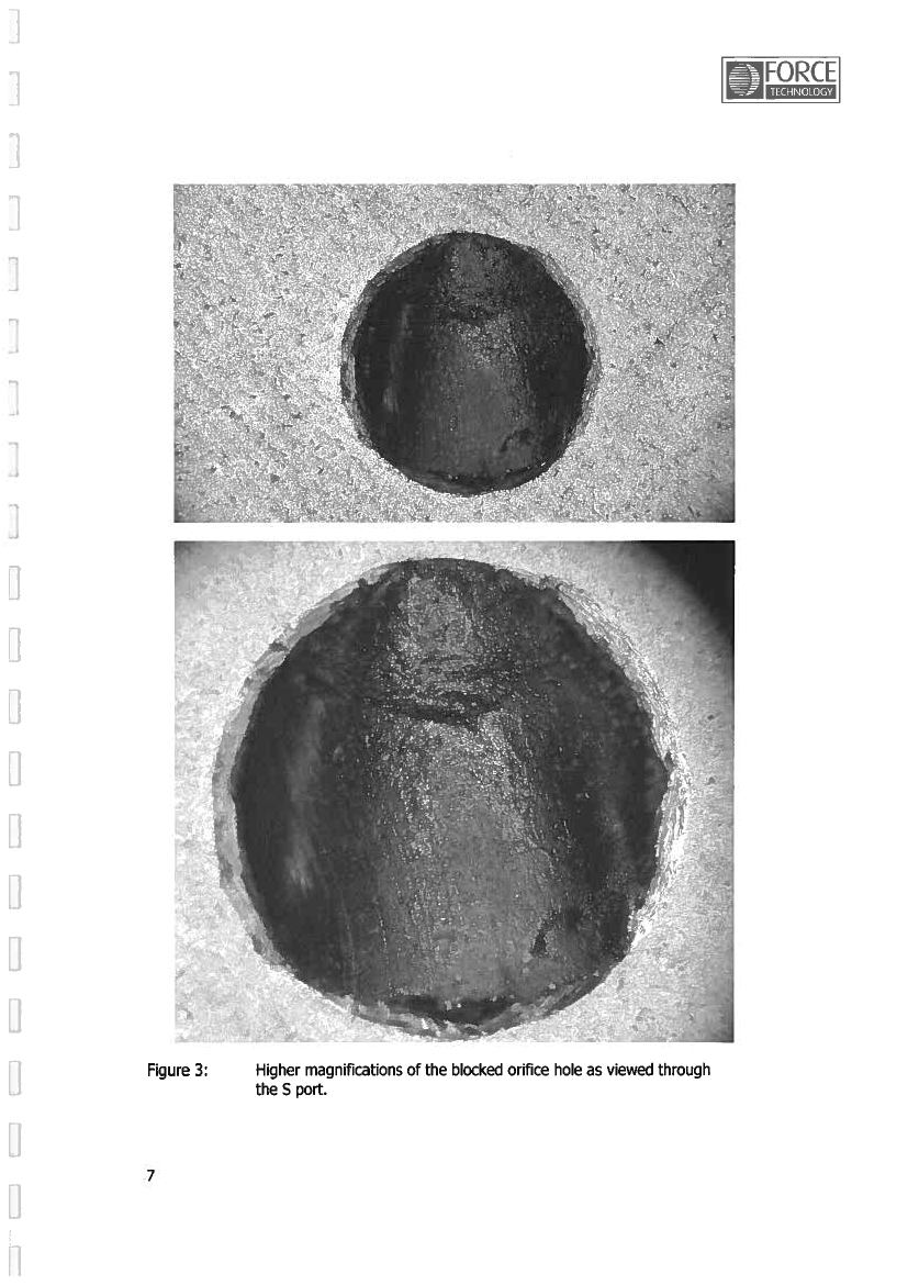
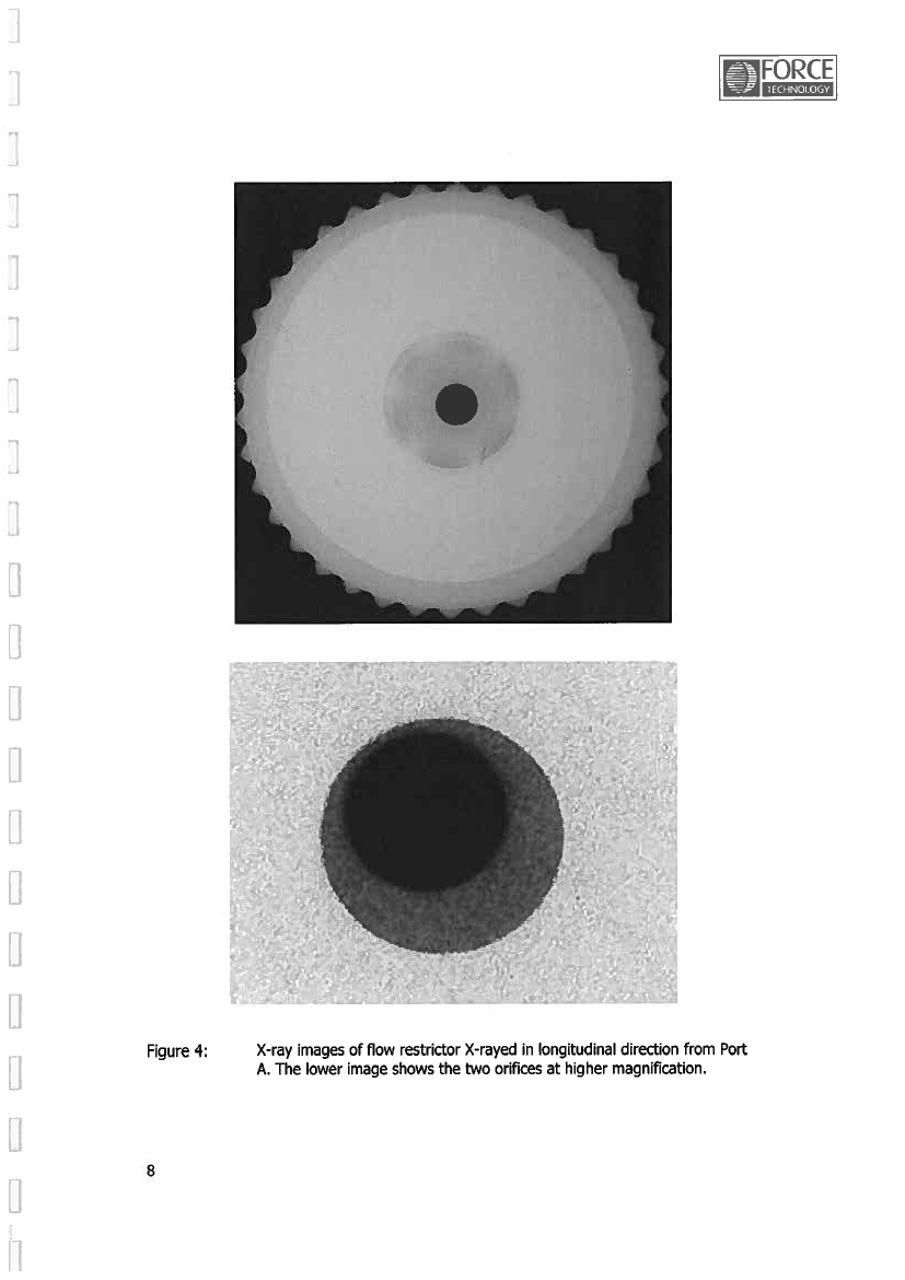
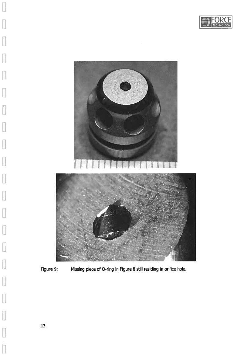
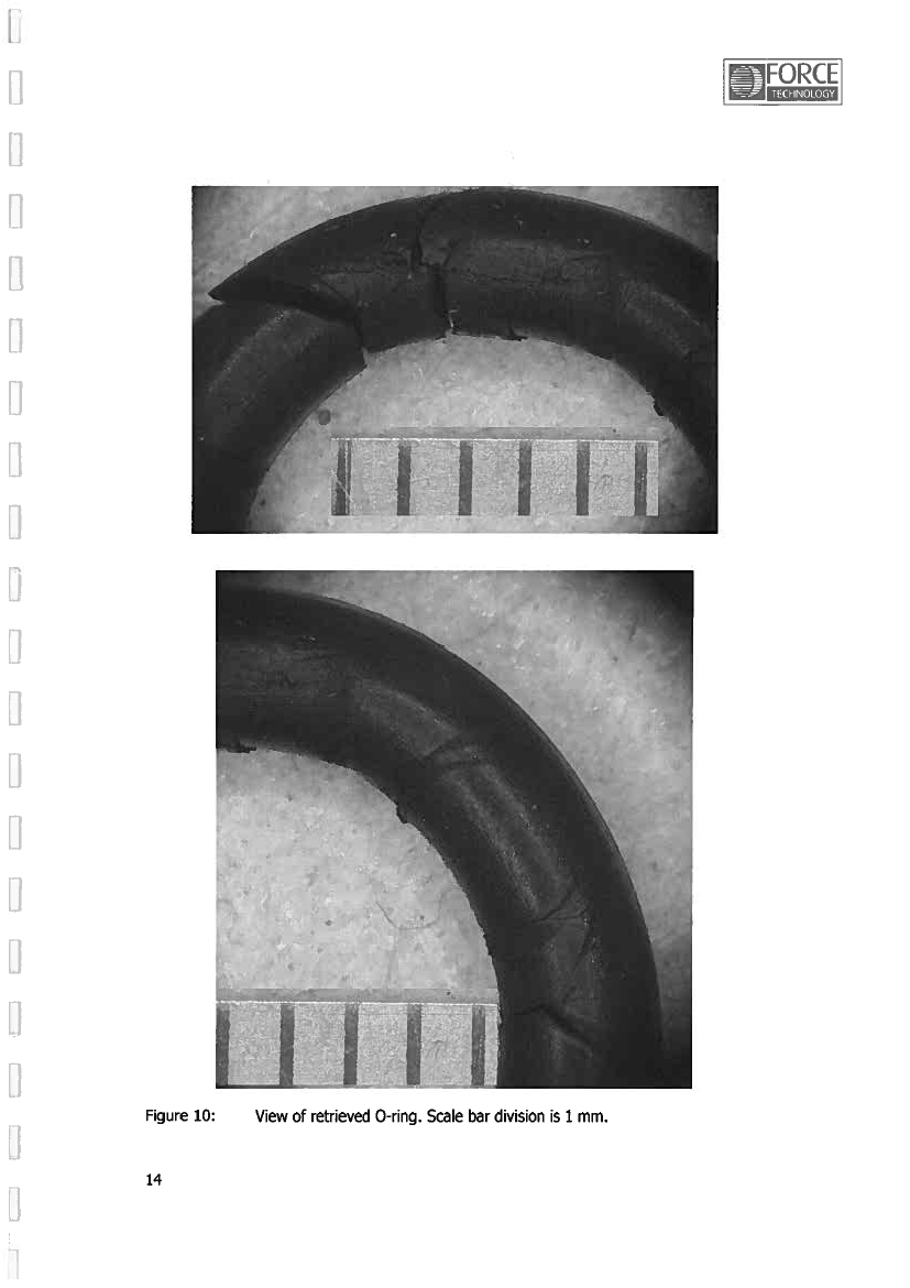
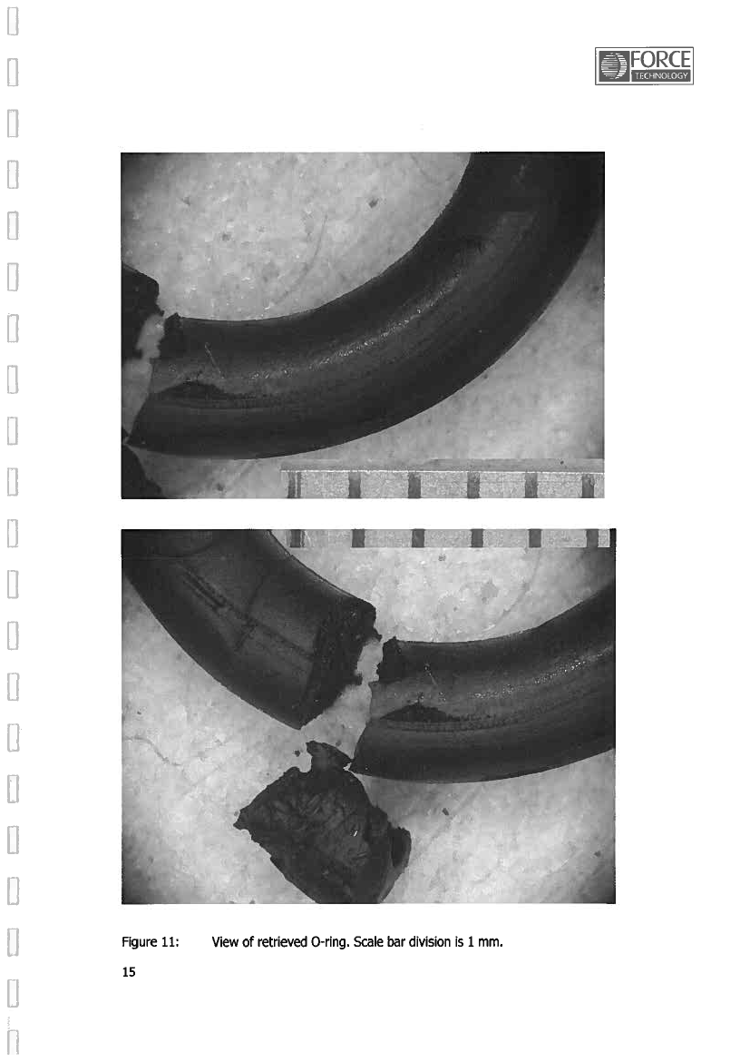
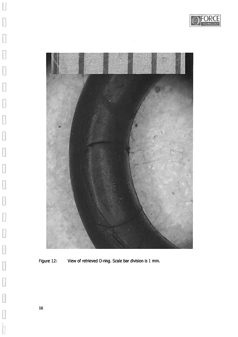
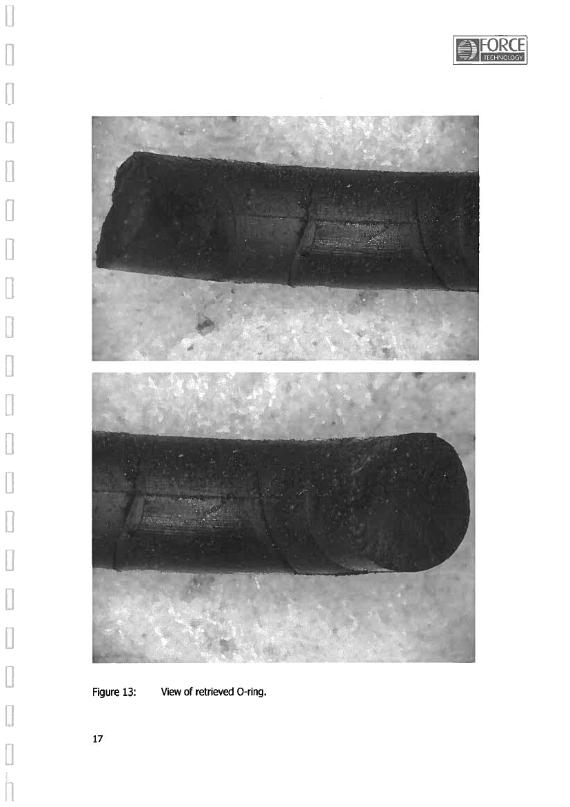
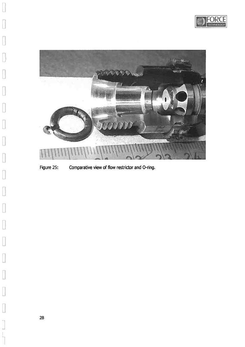
The extend port restrictor was removed and appeared to be clean as light could be seen through it.The Retract Port Restrictor was removed and appeared to be blocked, as light could not be seen through it.Fluids removed from the actuator retract and extend chambers contained particles and appeared to bediscolored.The actuator was disassembled and none of the findings could have caused the actuator to be blocked.1.12.5Retract Port Restrictor examinationA detailed examination report is enclosed as appendix D Retract Port Restrictor examination.Viewing down into the restrictor from the system side, it was evident that the orifice hole was blocked.X-ray examination did not reveal presence of any metallic particles or other x-ray absorbing material inthe flow channels of the restrictor.Removing the large orifice situated behind the Floating Valve in the restrictor allowed a view of the valveinterior. A broken O-ring was partly emerging through one of the flow relief holes. When the FloatingValve was removed from the restrictor housing, a damaged O-ring was found in four pieces. The smallorifice in the Floating Valve was blocked by a piece of O-ring material that matched the missing part ofthe No. 4 piece of O-ring (pictures below).
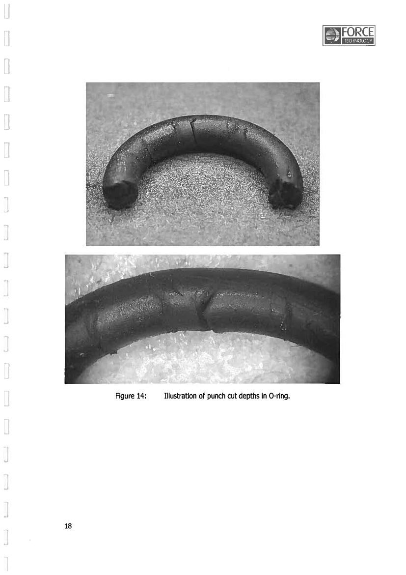
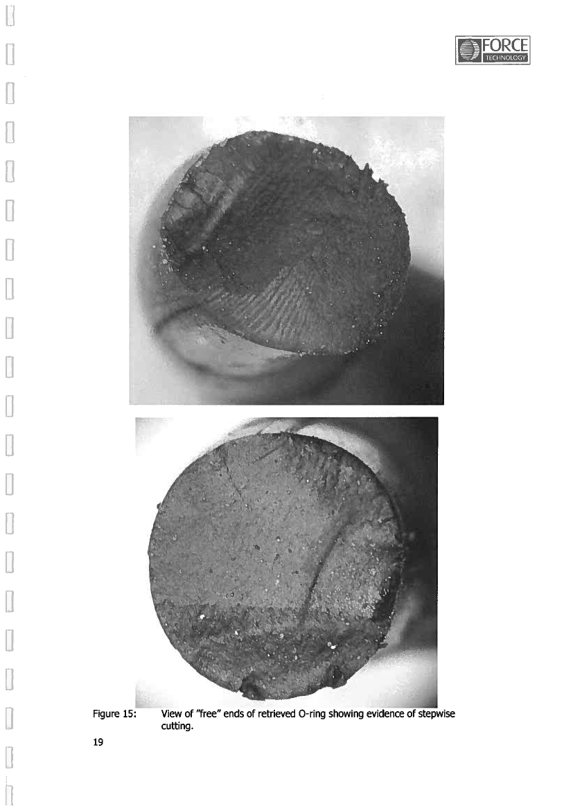
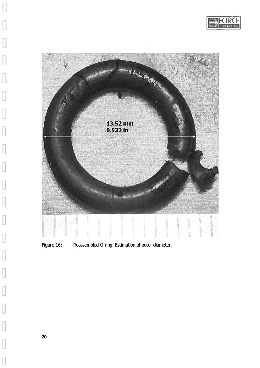
2134
Top left: Reassembled O-ring from thefour pieces found in the floating valve.Top right: The small orifice hole in thefloating valve is seen blocked by a pieceof the O-ring.Bottom left: A small bit of the O-ring wasalmost punched through the small orificehole and blocking it.
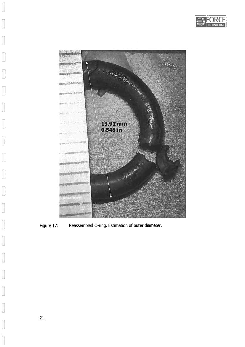
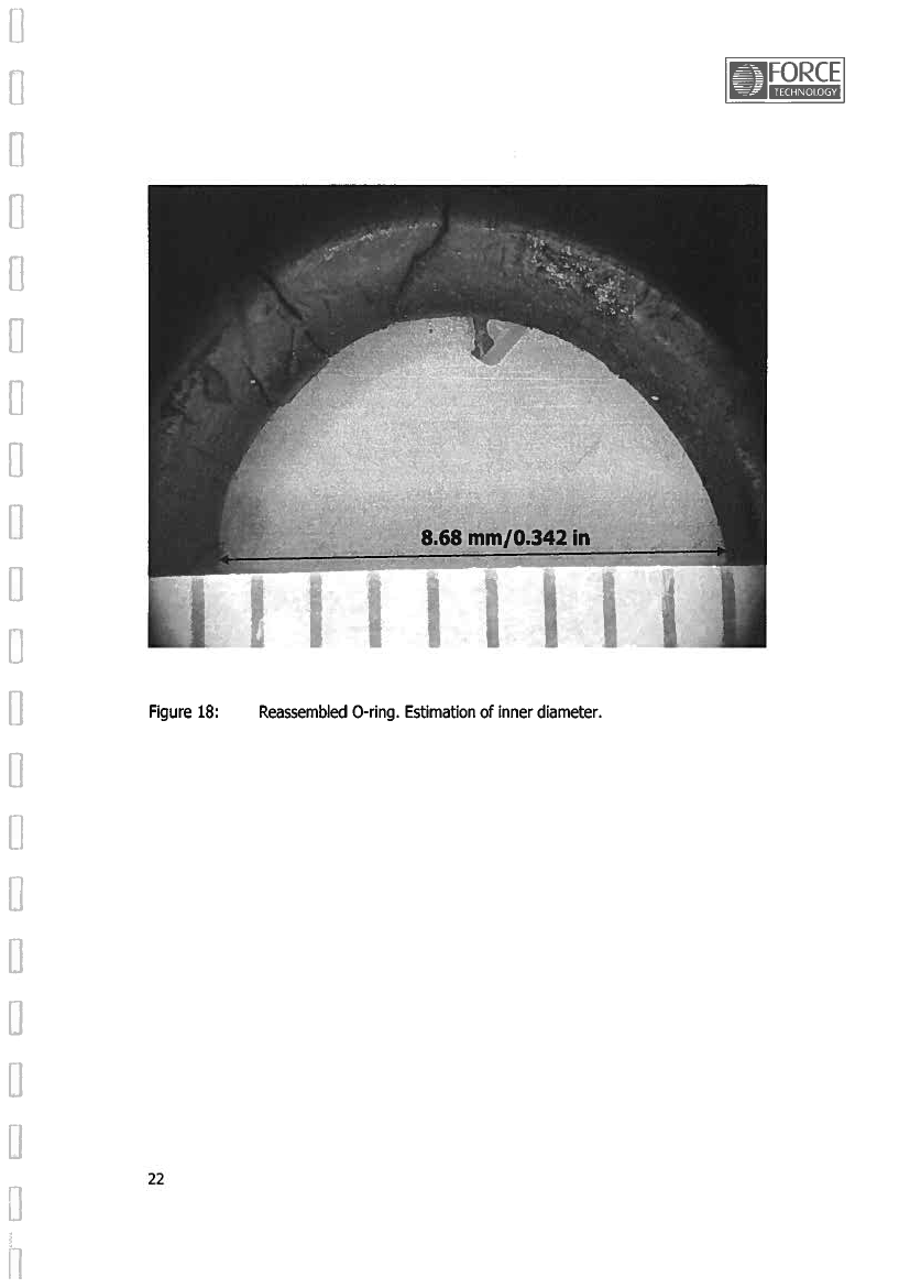
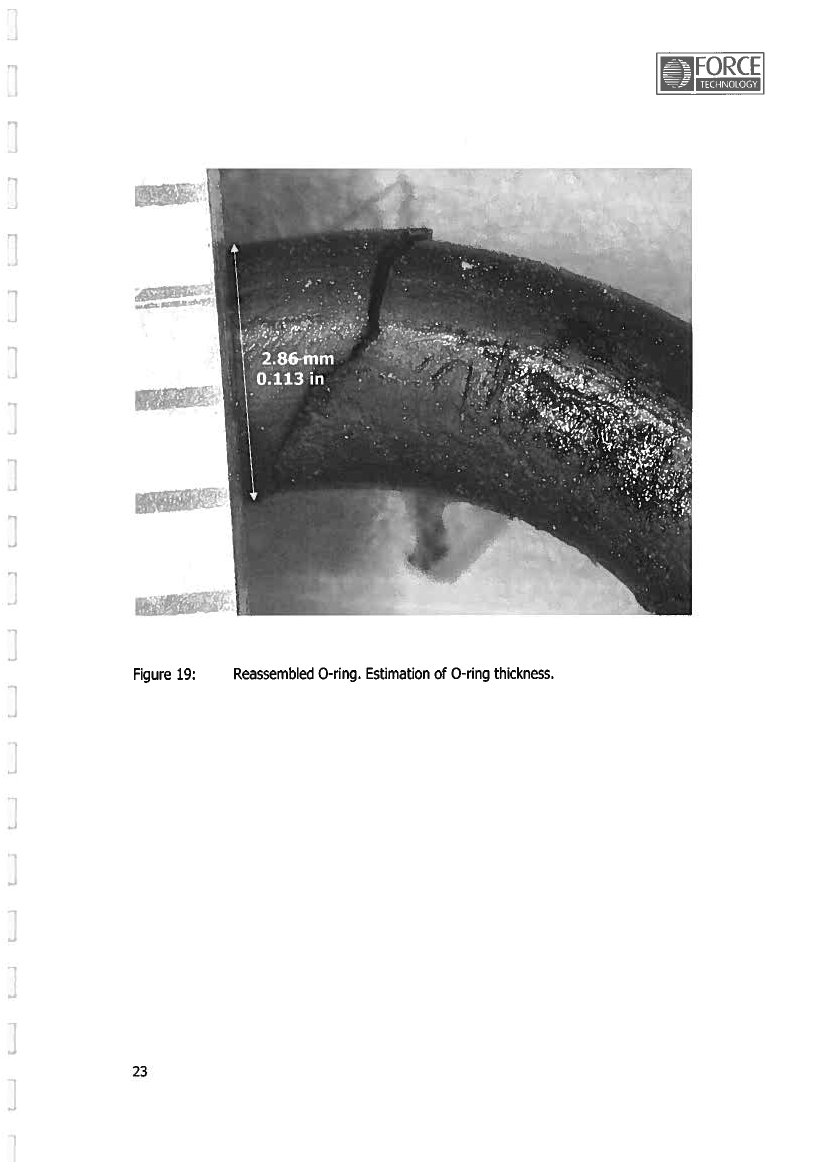
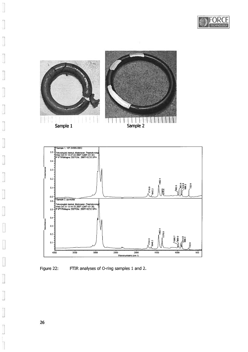
25
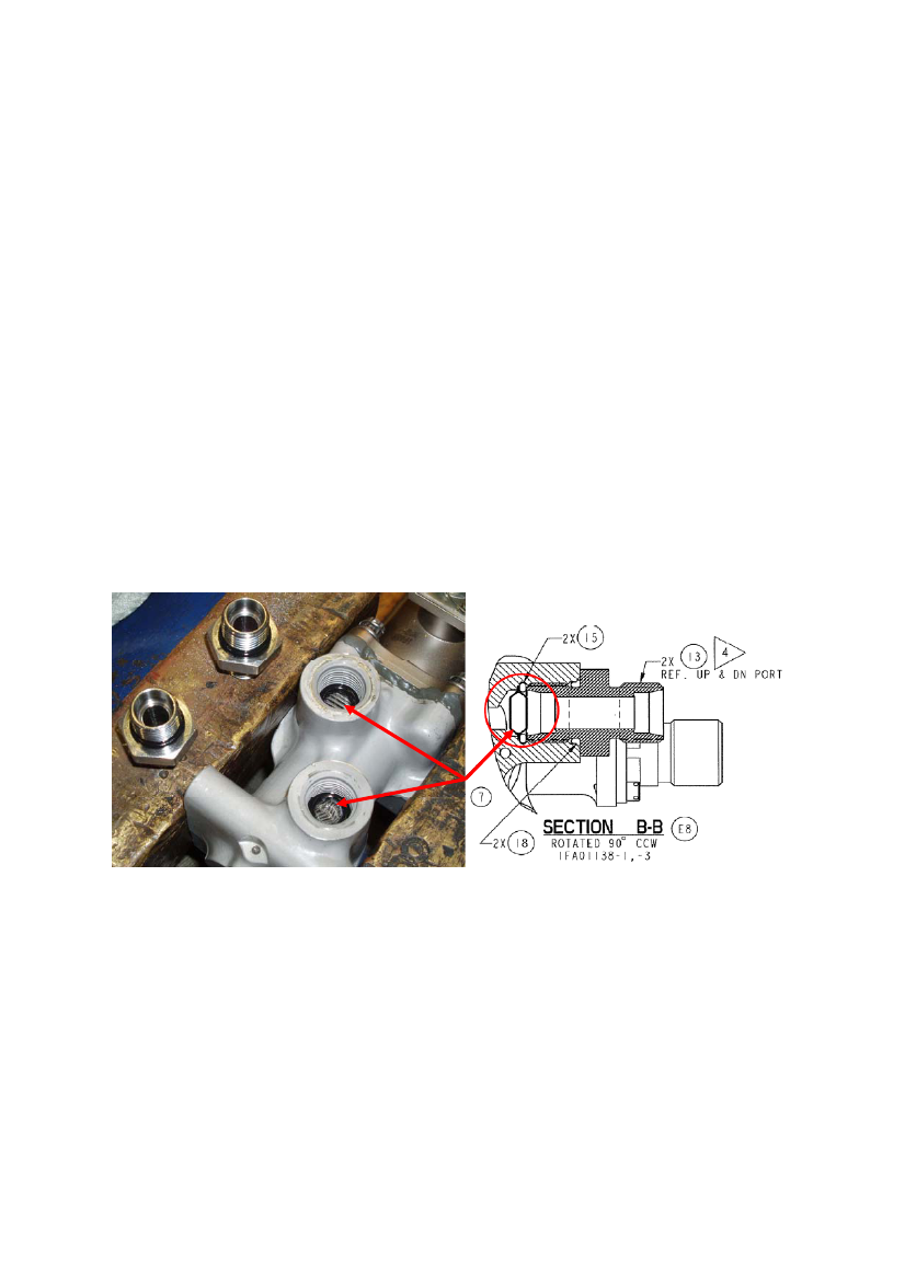
1.12.6Analysis of the rogue O-ringThe physical dimensions of the rogue O-ring was similar to that of the National Aerospace Standard P/NNAS1611-110 O-ring identified on the drawings for the door solenoid sequence valve (SSV). It wasfurther determined that the only component in the Landing Gear system that incorporated this type of O-ring was the SSV.NAS1611-110 O-rings were installed in the UP and DOWN ports of the SSV situated adjacent to a filterelement that protects the SSV.To establish similarity with the rogue O-ring, an O-ring was removed from a second SSV and wasexamined. The material analysis was carried out by means of infrared spectroscopy.The O-rings were found to be identical in both size and in material composition that was found to beEPDM (synthetic) rubber compounds.The O-ring dimensions according to the NAS specification sheet were:Inner diameter: 0.362 in (9.1948 mm) and cross section with: 0.103 in (2.6162 mm).1.12.7Solenoid Sequence Valve examination1.12.7.1Solenoid Sequence Valve S/N FAH-0200 examinationThe SSV S/N FAH-0200 that replaced S/N FAH-0083 on the 16thOctober 2007 was examined withoutleading to any findings or remarks. The O-rings P/N NAS1611-110 and the filter elements were in place inboth the up and down port of the valve as shown below.
SSV FAH-0200The filter element (7) and O-ring (15) in place in the up and down ports of the valve.The filter element and the O-ring are held in place by the union, flareless tube (13).
26
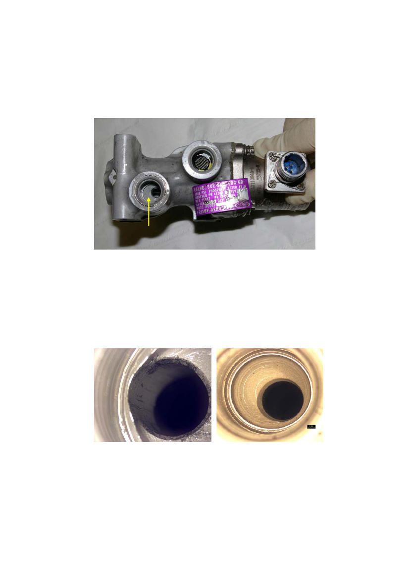
1.12.7.2Solenoid Sequence Valve S/N FAH-0083 examinationThe SSV removed from the aircraft on 16thOctober 2007 was sent to the Landing Gear manufacturer inCanada for refurbishment. In cooperation with the Transportation Safety Board of Canada, the AIBarranged the SSV to be examined in Canada.The examination revealed that the filter element and the O-ring were not present in the down port of theSSV (shown below).
Down port O-ring and filter element missing
Microscopic inspection of the down port, from which the filter and the O-ring were missing, showeddamage in form of linear score marks and nicks both inside the drill bore and around the entrance of thebore. For comparison, the up port O-ring and filter were removed and the up port inspected. This portshowed no evidence of damage.The down and up port drill bores is shown below.
Down port
Up port
27
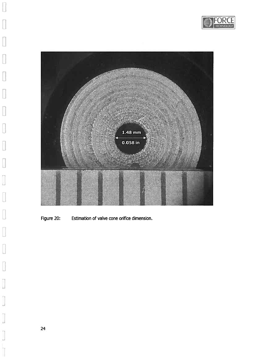
Examination of the SSV showed that passage of a cross section 0.103 +/- 0.003 inch O-ring (NAS1611-110) was not possible due to the sleeve hole diameter (0.069 inch/0.073 inch) inside the SSV.Sleeve from SSV S/N FAH-0083 and a NAS1611-110 O-ring are shown below.
The filter element or remains from the filter element was not found in the SSV or in filters of the No. 2hydraulic system.The investigation found no information revealing that it was observed and/or reported that the filterelement and the O-ring were missing from the down port of the replaced SSV S/N FAH-0083.1.12.7.3Solenoid Sequence Valve port filter element collapsesIn the course of the investigation, the AIB became aware that past occurrences showed that filter elementsin the SSV could collapse and migrate into the Landing Gear hydraulic system. In the past occurrences, O-Rings (situated adjacent to the filter) from the SSV´s are not known to have migrated into the LandingGear hydraulic system.Compression from the union, flareless tube on the O-ring is no longer present when a filter elementcollapse and moves away from the position behind the O-ring. This gives the O-ring the opportunity tomigrate into the Landing Gear hydraulic system.According to the manufacturer and order to solve this problem, a new type of filter element was underdevelopment when this accident occurred (reference: Appendix E).The investigation also became aware that the information regarding the SSV filter element collapsescenario was unknown to the maintenance personnel. The operator engineering department was inpossession of information on potential collapse of the SSV filters.
28
After the accident, an engineering order was initiated by the operator to remove 39 SSV’s from the DHC-8fleet. Inspection of these SSV’s (78 up and down ports) revealed the following findings up to andincluding 11thDecember 2007:•••••5 damaged filters.20 collapsed filters.3 missing filters.2 damaged O-rings.Color marking of the O-rings was not consistent (the picture of SSV S/N FAH-0200 illustrated insection 1.12.7.1 show O-rings without color markings and the picture of SSV S/N FAH-0083illustrated above in this section show a color marked O-ring). The O-ring found in the restrictorwas not color marked.
Finding examples from the above mentioned SSV inspections shown below.
Left:The filter element is damaged butstill in place behind the o-ring.Right:Collapsed filter element anddamaged o-ring.Below:Collapsed filter element migratedinto the SSV port drill bore.
1.12.8Main Landing Gear hydraulic system reviewA review of the aircraft hydraulic system concluded that the rogue O-ring could not travel from the SSV toits final location in the Retract Port Restrictor of the right MLG Retraction/Extension Actuator. Thisconclusion was supported by a detailed analysis of the other valves, in-line restrictors and fittings in thesystem between these two components.The analysis showed that while some of the hydraulic tubes would allow free passage of a rogue O-ring,other of the valve components, such as the Mechanical Sequence Valve (MSV) were of such a design thatthe O-ring could not pass through.29
The review of the hydraulic system revealed that the rogue O-ring from the SSV down port was able totravel between the SSV and the MSV and between the MSV and the Retract Port Restrictor installed onthe MLG Retraction/Extension Actuator. This is shown on the following drawing byredcolored lines.The sleeve was removed from the MSV. It was determined that the diameters of the sleeve holes at the upand down ports were less than the diameter of the NAS1611-110 O-ring. Furthermore the space inside thesleeve is minimized by the moveable spool operated by the Rear Door Actuator (illustrated below).
Retract restrictor
MSVUp-port
SSVDownport
NAS1611-110 O-ringshown for referenceSpoolMSV sleevepurposes
30
1.12.9Trouble shooting and maintenance actionsThe operator grounded its DHC-8 fleet on 11thSeptember 2007. This action was taken because theoperator suffered from two accidents where MLG Retraction/Extension Actuators were involved. Theaircraft was released as airworthy by the Civil Aviation Authorities and the first flight with LN-RDI aftergrounding was a test flight performed on 15thOctober 2007.According to the technical documentation, the following discrepancies were reported and handled in theperiod from 15thto 24thOctober 2007, which is showed on the following transcript of the maintenancerecords:Discrepancy reported on 15thOctober 2007:Corrective action:
On first retraction of landing gear right door and Right MLG door Solenoid Sequence Valveunsafe light stayed on much longer than left side. (installed in right MLG wheel well) replaced withserviceable valve, taken from same location fromA/C Reg.: LN-RDB.Part removed:Part installed:Solenoid SequenceSolenoid SequenceValveValveP/N: 48302-3P/N: 48302-3S/N: FAH-0083S/N: FAH-0200Date: 16.10.2007Date: 16.10.2007Discrepancies reported on 16thOctober 2007:1) During gear retraction, right gear door 5 sec.slower than left gear door and nose door.Corrective actions:1) Function test of landing gear performed acc. toAMM 32-31-00-720-801 found within limit.
2) At level flight (4000’) gear down selected. 2) Found target for right MLG down lock proxYellow gear door caution light right gear door sensor loose. Target replaced and test performedand red LDG unsafe light, also transit light in acc. AMM 32-31-00-720-801.gear handle on, visual check confirmed withindication after app 5 min flight 3 green LDGlights on LDG selector panel, also checked withLDG alternate extension gear green light in floor.After shut down right gear indication red.
31
Discrepancy reported on 17thOctober 2007:Functional test flight 4 x recycling of LDGperformed. First time gear light right main stayedon for 5 sec. longer than nose and left main door.Other cycles all normal.
Corrective action:Aircraft connected to ground hyd. cart. Multipleretraction extension functions completed IAWAMM 32-31-00 and alternate system function IAWAMM 32-34-00 no defects evident all indicationscorrect # 2 hyd. System bleeding IAW AMM 29-10-00. Ground cart removed.
Discrepancy reported on 20thOctober 2007:
Corrective actions:
Right gear doors closing 5-7 sec. later than other Right MLG door actuator replaced acc. AMM 32-doors.31-26-000-801.Part removedPart installedDoor ActuatorDoor ActuatorP/N: 46830-5P/N: 46830-5S/N: MAL-0307S/N: MAL-0095Date: 21.10.2007Date: 21.10.2007Right Mechanical Sequence Valve replaced acc.AMM 32-31-36-04.Part removedPart installedMechanical Sequence Mechanical SequenceValveValveP/N: 48303-103P/N: 48303-7S/N: FAH-0107S/N: FAH-0345Date: 22.10.2007Date: 22.10.2007Discrepancy reported on 22ndOctober 2007:Right MLG retraction slow.Corrective action:Alternate extension manifold filter checked ok,filter installed and alternate extension checkperformed.
32
Discrepancies reported on 24thOctober 2007:
Corrective actions:
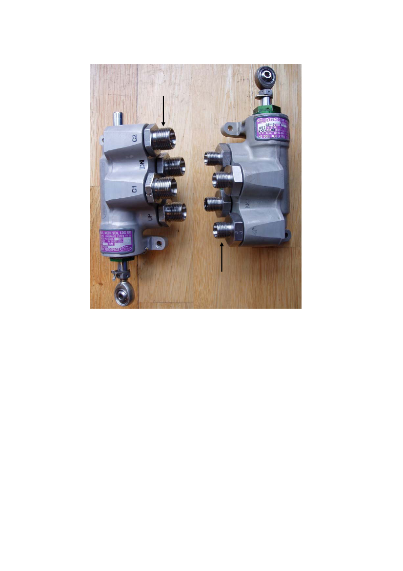
1) Test flight performed right MLG is very slow to 1) Right MLG MSV rigging checked, air bled fromextend more than 60 sec. perhaps 2 min.# 2 hyd system, 20 gear swings carried out andsystem bled no further defects evident.2) Right MLG door closing 5-7 sec. later thanother doors.2) MLG Retraction Extension Actuator replaced.Part removedPart installedMLG RetractionMLG RetractionExtension ActuatorExtension ActuatorP/N: 46550-9P/N: 46550-9S/N: MAL-0117S/N: MAL-0074Date: 24.10.2007Date: 24.10.2007Since the last maintenance action performed on 24thOctober 2007 until the accident occurred on 27thOctober 2007, the aircraft had completed a test flight on 25thOctober 2007 and 21 flight sectors withoutany reported discrepancies.1.12.10Mechanical Sequence Valve installationThe MSV S/N FAH-0345 that was installed on the aircraft right MLG at the time of the accident wasremoved from the aircraft and examined without it leading to any findings or remarks.According to the operator maintenance and logistic records, the MSV was identified as NLG MSV P/N48303-7 S/N FAH-0345. The Authorized Release Certificate following the MSV from stock alsoidentified the valve as NLG MSV P/N 48303-7 S/N FAH-0345.The MSV S/N FAH-0107 that was replaced on 22ndOctober 2007 was located and examined.The MSV was found to be configured with unions different from these attached to MSV S/N FAH-0345.There were no other findings or remarks.According to the operator technical and logistic documentation and the manufacturer aircraft S/N 4024Serialization List, the MSV was identified as Valve Body P/N 48303-103 S/N FAH-0107.Review of the Aircraft Illustrated Parts Catalog (IPC) revealed that the MSV Valve Body S/N FAH-0107was reconfigured as a MSV P/N 48303-7 intended for installation in the nose Landing Gear wheel well.The four unions were described as Reducer, flareless tube P/N MS21916J8-6.According to the aircraft records, the MSV Valve Body P/N 48303-103 S/N FAH-0107 had been installedon the aircraft since the aircraft was delivered from the manufacturer as new. The P/N 48303-103 was inthe IPC defined as a MSV Valve Body without Unions/Reducers.MSV S/N FAH-0345 compared to S/N FAH-0107 is shown on the following picture.Note: The MSV FAH-0107 is shown as it was found by the investigation team in the storage system.
33
Union, flareless tube (4 ea)Part No.: MS21902J8.
MSVMSVFAH-0345FAH-0107
Reducer, flareless tube (4 ea)Part No.: MS21916J8-6.
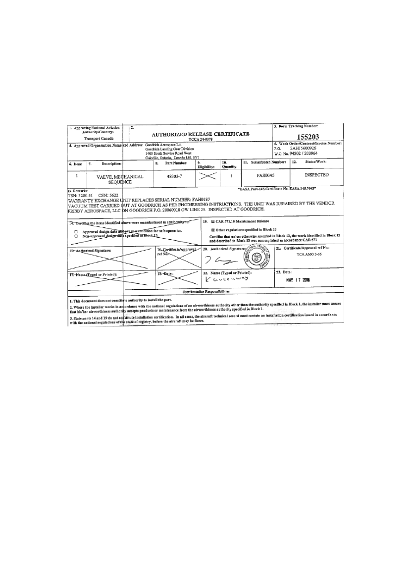
According to the maintenance records and the IPC, the replacement MSV, supplied from stock, was aNLG MSV P/N 48303-7 S/N FAH-0345 intended for installation in the NLG wheel well.Interview with the involved maintenance personnel revealed that prior to installation into the right MLGwheel well; the supplied MSV was reconfigured by the maintenance personnel.The Unions/Reducers were interchanged between the MSV’s.The Unions from MSV S/N FAH-0107, which were removed from the aircraft, were installed on thesupplied MSV S/N FAH-0345 converting this MSV from a P/N 48303-7 to a P/N 48303-5, which wascompatible with the installation requirements for the MLG wheel well.The picture comparing the two valves shows that the Reducers from the MSV P/N 48303-7 S/N FAH-345,supplied from stock, was installed on the MSV Valve Body P/N 48303-103 S/N FAH-0107, which wasremoved from the aircraft on 22ndOctober 2007.The NLG MSV P/N 48303-7 S/N FAH-0345 was identified and approved by the attached AuthorizedRelease Certificate issued by the landing gear manufacturer on May 17th2006.34
No approved reconfiguration procedure was found in the Aircraft Maintenance Manual (AMM) or in anyother approved aircraft maintenance documents.NLG MSV P/N 48303-7 S/N FAH-0345 Authorized Release Certificate shown below.
35
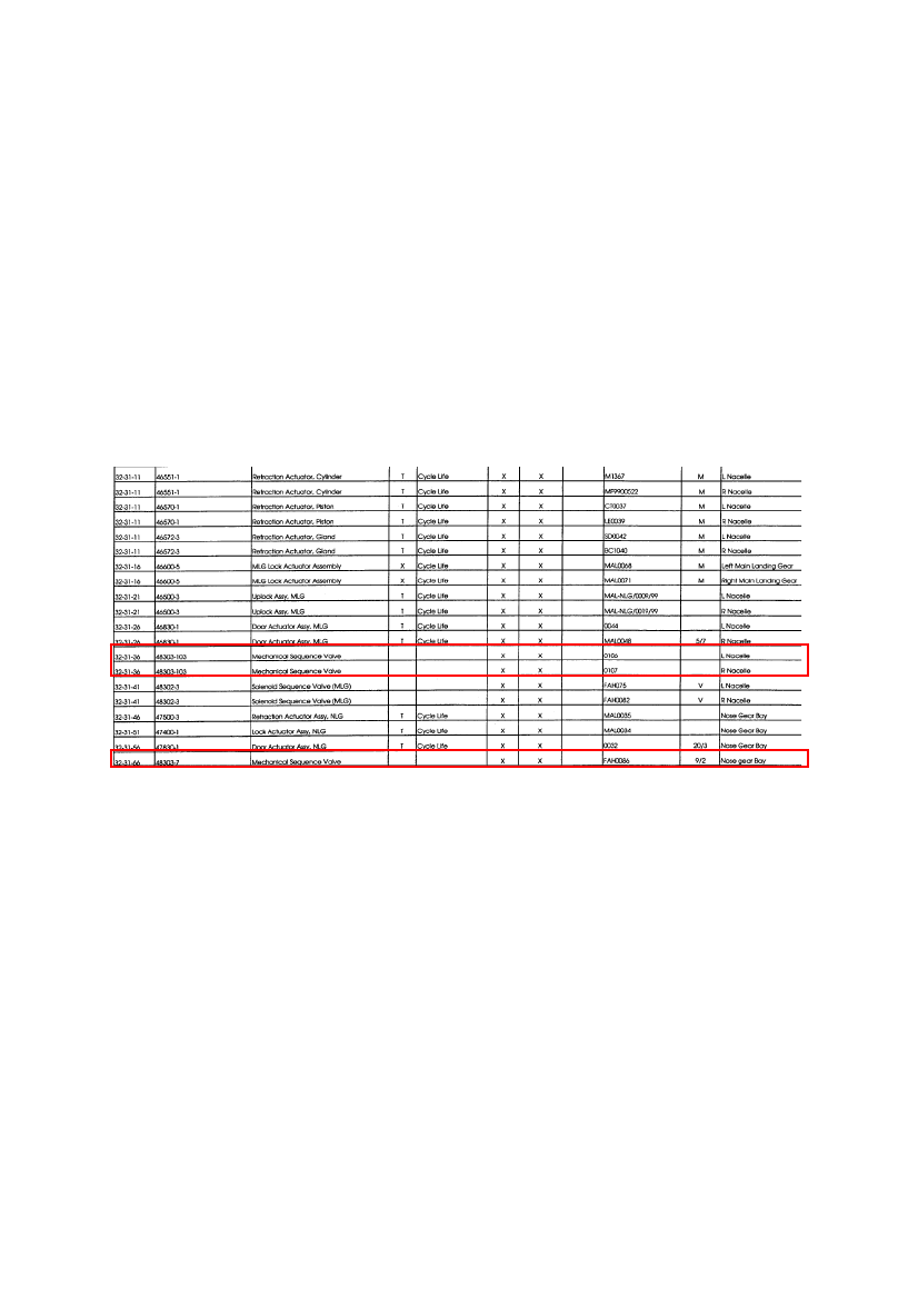
1.12.11Mechanical Sequence Valve Identification and Registration1.12.11.1 GeneralThe manufacturer’s documentation adhered to Air Transport Association of America (ATA) Specification100 – Specification for Manufacturers Technical Data.Among other texts the ATA document chapter 2-4. Aircraft Illustrated Parts Catalog. Section 2-4-0. Policywrites in general:“A) The Illustrated Parts Catalog is intended for use in the identification and requisition of replaceableaircraft parts and units. It is a companion document to the Aircraft Maintenance Manual and shallcontain all parts information for which maintenance practices coverage has been provided.”“B) It shall also contain all those individual line-replaceable units such as light bulbs, sockets, lenses,caps, seals, bearings, screens, screws, filters, electrical connectors, circuit cards, relays, pulleys, fittings,brackets, external lines and all components and/or parts where maintenance practices allow replacementof the components or parts rather than replacement of the next higher assembly.”“C) If a specific part is to be locally manufactured from raw (bulk) stock such as cut lengths of conduit,bonded braid, upholstery cloth, gasket material, rubber extrusion, etc., it shall be clearly stated.”1.12.11.2 Manufacturer’s parts documentationAt the time of delivery of the aircraft, a Serialization List by ATA chapter was compiled by the aircraftmanufacturer for the operator of the DHC-8 aircraft S/N 4024.
36
Extract from the aircraft S/N 4024 Serialization list regarding ATA chapter 32 is shown following.A. ATA chapter.B. P/N.C. Description.D. Life time component.E. Manufacturing date (life limit according to).F. Serial (serialized component).G. Interchangeable.H. Replaceable.I. S/N.J. Verified.K. Location on aircraft.
A
B
C
D
E
F
G
H
I
J
K
According to the list ATA number 32-31-36 MSV Valve Body P/N 48303-103 was installed in both MLGwheel wells and ATA number 32-31-66 MSV P/N 48303-7 was installed in the NLG wheel well duringdelivery of the aircraft.Compared to a life limited component, like the ATA 32-31-46 Retraction Actuator Assy, NLG, which hada cycle life limit, the list indicates (D and E blank) the MSV’s as components life on condition.No Component Maintenance Manual (CMM) for the MSV was available in the maintenance system.
37
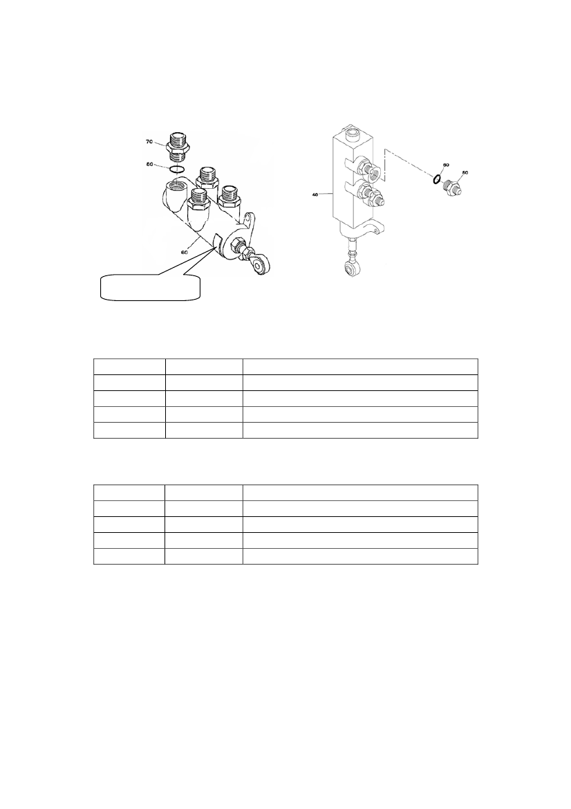
Review of the IPC revealed the following information about the MSV’s:The IPC describes some items as “itemnot illustrated”.Item 10 mentioned in the list is such an item.
Identification plate
32-31-36-01 MLG Doors Mechanical Sequence ValveFigure Item10607080Part Number48303-548303-103MS21902J8NAS1612-8ADescriptionValve, Mechanical SequenceValve, BodyUnion, Flareless TubeO-Ring
32-31-66-01 NLG Doors Mechanical Sequence ValveFigure Item10405060Part Number48303-748303-103MS21916J8-6NAS1612-8ADescriptionValve, Mechanical SequenceValve, BodyReducer, Flareless TubeO-Ring
38
The identification plates fitted to the MSV’s describe the valves as MSV Valve Body P/N 48303-103regardless of the type of Unions/Reducers that were installed.The following pictures show the identification plates fitted to the MSV S/N FAH-345 and FAH-0107.
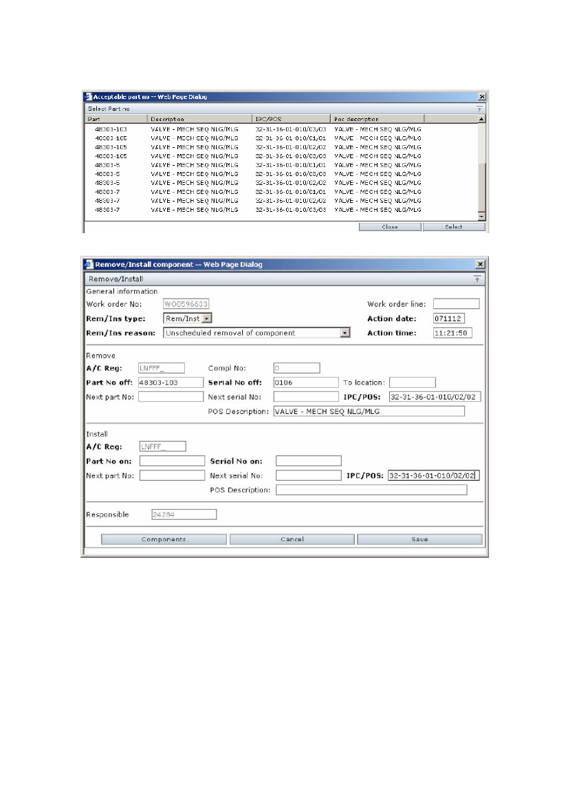
1.12.11.3 Information given by the operators computerized data support systemsThe operators Maintenance Management Information System (MMIS) and its subsystems handle actionsrelated maintenance and configuration control.According to the operator, the registration of components into the data support system at the time when theDHC-8 aircraft were introduced was based on the Aircraft Serialization List compiled by themanufacturer.When the data was transferred in 2006 from the origin data support system to the system used at the timeof the accident, the operator decided that there was no reason to verify that the basic data in the originsystem was correct, only that a fully accurate transfer of data into the new data support system wasaccomplished.In the data system it was found that the MSV P/N 48303-103, -5 and -7 was registered as interchangeableparts that could be installed in the positions NLG/MLG.Position 01 = NLG position.Position 02 = MLG left position.Position 03 = MLG right position.
39
An extract from the operator data system is shown following (P/N 48303-105 is not in production).
It appeared on the extract from the data system that on 12thNovember 2007 (post the accident) P/N 48303-103 S/N 0106 (FAH-0106) was removed from the aircraft POS 02.It is shown that the position description is both NLG and MLG.
40
The following data lists from the operator shows the MSV Installed Serial Numbers selected as P/N48303-103, -5 and -7 was made available for review on 5thNovember 2007.According to the list, MSV Valve Body P/N 48303-103 was registered as installed on the mentionedaircraft in both NLG (01) and MLG (02/03) positions.According to the list MLG MSV P/N 48303-5 was registered as installed on the mentioned aircraft inMLG positions except S/N FAH-0152 that was registered as installed in the NLG position.According to the list NLG MSV P/N 48303-7 was registered as installed on the mentioned aircraft in NLGposition except S/N FAH-0345 that was registered as installed in the MLG right position on the accidentaircraft at the time of the accident.The lists are shown below.MSV Valve Body P/N 48303-103.
41
MLG MSV P/N 48303-05
NLG MSV P/N 48303-07.
Review of the spare part handling data system revealed that there were two MSV’s on stock inCopenhagen on the 20thOctober 2007. Both valves on stock were NLG MSV P/N 48303-7.The data system also revealed that MSV’s replaced by the maintenance personnel was returned to thestock system as MSV Valve Body P/N 48303-103.The Logistics Tag concerning the MSV replacement on 22ndOctober 2007 was examined. It was foundthat the P/N out was at first written as P/N 48303-7 but, this P/N was afterwards deleted and rewritten asP/N 48303-103.The maintenance personnel explained that they used the identification plate fitted to the MSV as referencewhen they fulfilled the paperwork following the replaced valve back to the stock system.42
The data system showed P/N 48303-5 / -7 out-going from stock and P/N 48303-103 as replaced partreturned to the stock system.The Authorized Release Certificate issued by the Landing Gear manufacturer following the MSV’sidentified the valves as P/N 48303-5 or -7 despite P/N 48303-103 was printed on the identification platesfitted to the valves. The identification of the valves could be verified via the S/N that was printed both inthe certificate and on the valve.1.12.12Mechanical Sequence Valve reconfigurationRegarding the MSV reconfiguration, the involved maintenance personnel were interviewed and the workprocess was identified.The maintenance organization and the maintenance supervisor were of the opinion that the MSV’s wereinterchangeable as it appeared from the operator data system. The maintenance personnel were told tochange the configuration of the delivered NLG MSV to fit into the MLG position.Rgarding replacement of the Unions fitted to the MSV Valve Body P/N 48303-103, the maintenanceorganization found no information in the Aircraft Maintenance Manual.However, the organization did find information in the IPC indicating that the Union (item 70) and the O-ring (item 80) could be replaced if necessary indicating that standard maintenance practices allowreplacement of fittings, gaskets and O-rings rather than replacement of the assembly.The maintenance organization was of the opinion that the MSV Unions and the O-rings underneath themwere such line-replaceable parts and therefore the decision and action to change the Unions on the NLGMSV S/N FAH-0345 was approved in accordance to standard maintenance practices.The maintenance personnel informed the AIB that the MSV S/N FAH-0107 was removed from the aircraftby another shift. They were told to interchange the Unions between the removed MSV and a new MSVthat was delivered from stock and placed on a table in the hangar.The maintenance personnel were not involved in the trouble shooting process on the aircraft.The AIB was told by the mechanic that removed the Unions from the old MSV that they were dirty.Before installation on the new MSV S/N FAH-0345, the Unions were cleaned. It was the opinion of themechanic that if an O-ring was hidden inside one of the Unions, it would have been observed. Themechanic that removed the Unions was not DHC-8 type rated as a mechanic. However, a company DHC-8course was completed. The mechanic had no MSV inspection procedures available but, it was stronglyexpressed to the AIB that work always was done in a meticulous way and that before installation, partswere always inspected. The Unions were inspected and it was expressed that no O-ring were hidden insideany of them.The four Unions were of the same type and size therefore the mechanic fitted the Unions to the MSV inrandom order.To illustrate that it was possible for an O-ring NAS1611-110 to be transferred via the Unions, the AIBplaced an O-ring inside the Union as shown in the pictures below.
43
O-ring
O-ring
Union, Flareless Tube P/N MS21902J8and O-ring P/N NAS1611-110 is shown incomparison.The O-ring is shown placed inside theUnion illustration purposes only.O-ringO-ring
1.13Medical and pathological informationNo further information.1.14FireAccording to a security video recording there was some sparks and smoke originating from the aftfuselage as the aircraft made contact with the runway surface, but there was no fire.
44
1.15Survival aspectsAs mentioned in Section 1.12.1, the right engine was shut down by the flight crew before landing tominimize the risk of propeller blade or blade debris separation and penetration into the cabin area fuselage.Four propeller blades were damaged while skidding on the runway asphalt (following picture), but nodebris separations from the engine or the non powered propeller occurred and the fuselage surrounding thecabin area was undamaged.
When the aircraft came to rest on taxiway C area the first cabin door (Left Forward) was opened at1453:13 hrs and the first crew member was outside the aircraft at 1453:15 hrs. The crew member tookposition to the left of the door, assisting the passengers out of the aircraft and guided the passengers awayfrom the aircraft. The left aft cabin door was opened a second later and the passengers were directed in thesame direction away from the aircraft. The two right cabin doors were not used during the evacuation.The first fire fighters arrived at the scene at 1453:21 hrs.Evacuation requirements written in JAR and FAR Sec. 25.803: “Itmust be demonstrated that when theaircraft is at maximum seating capacity, the aircraft, including the crewmembers, can be evacuated to theground under simulated conditions within 90 seconds”.The aircraft was evacuated in 50 seconds. The last person that left the aircraft was the first officer.During the accident, the data from the FDR showed that the maximum vertical, lateral and longitudinal Gforces were 1.30 G, -0.09 G and -0.48 G respectively.The airframe did not exceed the certification requirements specified by Joint Aviation Regulation (JAR)and Federal Aviation Regulation (FAR) Sec. 25.561 (9 G forward, 3 G upward, 3 G sideward on theairframe and 4 G on the seats and their attachments). These requirements were established to ensure thatunder these loads each occupant has every reasonable chance of avoiding serious injury in a minor crashlanding and also that heavy items in the passenger cabin do not become deformed in any manner thatwould impede subsequent rapid evacuation of the occupants.Four of the seat meal tables next to the aisle were found deployed (i.e. meal serving position).As mentioned in the Accident Report HCLJ510-000433 published by the AIB Denmark regarding anaccident to another DHC-8 aircraft on 9thSeptember 2007, the latch of the tables was found slack and easy45
to move. The latch could rotate both to the left and to the right. All four latch pins was found movedtowards the aisle and therefore the tables could have been released either by the person who left thewindow seat or who left the seat next to the aisle during the emergency evacuation of the aircraft.1.16Tests and researchNo tests and research were done.1.17Organizational and management informationThe maintenance organization was EASA Part-145 Category A approved.For instance, the A class rating means; that the Part-145 approved maintenance organization may carry outmaintenance on aircraft and any component (including engines/APU’s) only whilst such components arefitted to the aircraft.1.18Additional informationIn this report there are references to:The AIB Denmark Report HCLJ510-000433 regarding the accident to Bombardier DHC-8-400registration LN-RDK at Aalborg Airport (EKYT) Denmark on 9thSeptember 2007.The report was published in 2009 and is available on http://www.aib.dk1.19Useful or effective investigation techniquesNo new techniques were used during this investigation.
46
2.Analysis2.1Flight crewThe flight crew was properly licensed.2.2The aircraftThe aircraft had a valid certificate of airworthiness. The aircraft maintenance records were in compliancewith the established maintenance program.The aircraft was within the mass and balance limitations.2.3The Quick Reference Handbook (QRH)During the final approach and landing, continuous GPWS warnings sounded. The AIB considerscontinuous warnings to be a mental stress factor increasing flight crew workload.The AIB found, analysing the information from the CVR, that the Emergency Landing checklist was notperformed by the flight crew. This is based on the fact that if the checklist was performed the GPWScircuit breakers would have been pulled in order to avoid continuous GPWS warnings. The AlternateLanding Gear Extension checklist did not contain this information.The AIB finds it appropriate that the Alternate Landing Gear Extension checklist, in case of not solving anunsafe gear situation, contains information and/or references to the Emergency Landing checklist asguidance to the flight crew.There are no certification requirements for the checklists (manufacturers and/or operators) to refer to otherrelevant checklists. However, it is the opinion of the AIB that helpful information and/or references mightimprove flight safety despite that minimum requirement is fulfilled.For that reason, it is the opinion of the AIB that a more appropriate checklist structure could havecontributed to a reduction of a high flight crew workload.The above mentioned issues were also issues in the AIB investigation of the DHC-8 accident at AalborgAirport on September 9th2007 (report HCLJ510-000433).2.4WeatherThe weather at the time of the accident was VMC and did not influence the sequence of events.2.5Navigation aidsAt the time of the accident, all navigation aids were functioning without any remarks and did not influencethe sequence of events.2.6CommunicationAt 14:07:38 hrs the commander informed Approach that the landing would be an Emergency Landing.The flight crew was in radio contact with ATC using the normal routine frequencies until 14:20:09 hrs. Atthat time on request from the first officer, the flight was assigned its unique controller, Kastrup Final(119.100 MHz). The flight remained on that frequency (119.100 MHz) through the remainder of the flight.47
The AIB found that the flight crew was very busy in the above mentioned period. For that reason, somecommunication from Copenhagen Approach was missed by the flight crew.The AIB is of the opinion that the flight crew, ATC and the airport Rescue and Fire Fighting Service hadthe understanding that a mayday call in some way was declared by the flight crew.The communication between the flight crew and ATC did not influence the sequence of events.2.7FireThere was no fire.2.8Survival aspectsIn general, lessons learned from the accident in Aalborg seemed to assist the crew in handling theemergency (aircraft and passengers).The right engine was shut down by the flight crew before landing to minimize the risk of propeller bladeor blade debris separation and penetration into the fuselage surrounding the cabin area.No debris separated from the non powered propeller.In relation to survival/injury aspects the AIB found the decision to shut down the right engine wasappropriate in this situation.The latches securing the seat meal tables in the stowed position were found to be slack and easy to rotate.The AIB found seat meal tables released which could be influential on the evacuation of the aircraft.Passengers seated next to the window could find it difficult to leave the seat row if the tables were inreleased position.The above mentioned issue was also an issue in the AIB investigation of the DHC-8 accident at AalborgAirport on September 9th2007 (report HCLJ510-000433).The preparations that were done by the crew lead the evacuation of the aircraft to be optimum.The accident was survivable.2.9Right Main Landing Gear (MLG) stuckAt the place of the accident, the MLG was found to be released from the up-lock hook but stuck in almostup position. It was impossible to extend the right MLG further down without dismantling the MLGRetraction/Extension Actuator from the MLG yoke cross beam.When the actuator was replaced with an actuator taken from another aircraft the operational function of theMLG system was found to be normal as per design specifications.
48
A detailed examination of the MLG Retraction/Extension Actuator found that the Retract Port Restrictorwas blocked by a rogue O-ring. This blockage in the single line hydraulic system caused the actuator to behydraulically locked.The hydraulic lock of the actuator caused the MLG to be stuck and impossible to extend into landingconfiguration.The investigation reveled that the port restrictors on the actuator had no protection against contaminationin the hydraulic line system. Any contamination caused by released parts from the components within theMLG hydraulic system or foreign objects introduced during maintenance could block one of the restrictorsand cause the actuator to be hydraulically locked.2.10Origin, transfer and travelling of the rogue O-ringThe rogue O-ring found in the Retract Port Restrictor was found to be a P/N NAS1611-110 and it wasdetermined that the only component in the right MLG system that incorporated this type of O-ring was theright MLG Solenoid Sequence Valve (SSV).The SSV S/N FAH-0200 installed in the right wheel well was examined. It was found that all the O-ringsNAS1611-110 were in place in the ports of the valve.The aircraft technical records showed that the valve recently was replaced. The investigation tracked downthe replaced valve that was found to be SSV S/N FAH-0083.Examination of the SSV FAH-0083 that was replaced on 16thOctober 2007 revealed that the filter elementand the NAS1611-110 O-ring were not present in the down port of the SSV as it should be.Although it could not be determined with any degree of certainty that the origin of the O-ring found in theRetract Port Restrictor was from the SSV FAH-0083, the conclusion of the AIB is in the light of the factthat the investigation found no other possibilities that the origin of the O-ring was from the SSV FAH-0083.During the investigation, the AIB revealed that filter element collapse during normal operation of theLanding Gear was not uncommon. The investigation also revealed that when the filter element collapses,the O-ring located adjacent to the filter element looses compression. This situation gave the O-ring thepossibility to move out of its position and migrate into the Landing Gear hydraulic system. Therefore, theAIB is of the opinion that the SSV down port and up port filter elements may not withstand normalLanding Gear hydraulic operational pressure fluctuations and may collapse.Since the test flight of LN-RDI on 15thOctober 2007 until the accident occurred a sequence ofdiscrepancies regarding the function of the right MLG were reported.The AIB can not exclude or conclude that these technical problems were related to the O-ring that wasfound inside the Retract Port Restrictor of the MLG Retraction/Extension Actuator.The O-ring that had travelled inside the hydraulic lines could have restricted the hydraulic fluid flow moreor less during MLG operations.It must be added that the aircraft manufacturer had no previous knowledge of specific details that mayarise as a result of an O-ring dislodging after the port filter element collapsed.49
Looking at the design and the function of the valves contained within the landing gear hydraulic system itis evident that the discrepancies mentioned during the test flight and the trouble shooting period, aresymptomatic of issues related to one or more of these valves. Therefore, the AIB found it natural tosuspect and replace a valve as part of trouble shooting before looking into other areas of the hydraulicsystem.There was no reason to inspect the ports of the valve SSV FAH-0083 that was replaced, which probablyexplains why no one involved in the handling of the valve observed and/or reported that the filter elementand the O-ring were missing from the down port of the valve.The AIB can not exclude or conclude that the accident could have been prevented if the trouble shootershad found the filter element and the O-ring missing when they replaced the SSV FAH-0083 on 16thOctober 2007.On 24thOctober 2007 during a test flight, it was reported that the right MLG was very slow to extend andthat the MLG doors were late to close. The AIB can not exclude or conclude that this problem was causedby the O-ring travelling inside the hydraulic lines reducing the hydraulic fluid flow. This is based on thefact that the maintenance action in this case was to replace the MLG Retraction/Extension Actuator.Since the above mentioned maintenance action was performed on 24thOctober 2007 until the accident on27thOctober 2007 the aircraft had completed a test flight on 25thOctober 2007 and 21 flight sectorswithout any reported discrepancies. In this period the O-ring was somewhere inside the hydraulic linebetween the MSV and the MLG Retraction/Extension Actuator.Examination of the valves, in-line restrictors, fittings and lines revealed that space available to the size ofthe NAS1611-110 O-ring was limited.The O-ring was able to travel inside the hydraulic lines between the SSV and the Mechanical SequenceValve (MSV), as well as inside the hydraulic lines between the MSV and the Retract Port Restrictor of theMLG Retraction/Extension Actuator.The MSV and the other parts of the system were of such a design that the O-ring could not pass through.It is unknown to the AIB when the filter and the O-ring migrated from the SSV that was replaced on 16thOctober and migrated into the hydraulic system. The fact that the O-ring was missing in the down port ofthe removed valve and that the MLG was reported to operate slowly from time to time strongly indicatesthat the system was affected by the travelling O-ring in the hydraulic lines of the system.The AIB found it impossible for the released O-ring to pass through the MSV positioned in the hydraulicline between the SSV and the MLG Retraction/Extension Actuator Retract Port Restrictor. However, theMSV was replaced on 22ndOctober 2007 which caused the investigation to concentrate on a possible wayof transferring the O-ring from one side of the valve to the other side of the valve.It was found that the new MSV supplied was a NLG MSV P/N 48303-7 S/N FAH-0345 having Reducersinstalled to fit the NLG. These Reducers were interchanged with the Unions taken from the MSV ValveBody P/N 48303-103 S/N FAH-0107 that was removed from the right MLG.50
The AIB is of the opinion that, the O-ring was transferred while trapped inside one of these Unions.The AIB found that this was the only way the O-ring could be transferred from one side of the MSV to theother side of the MSV given the possibility to travel between the MSV and the MLG Retraction/ExtensionActuator Retract Port Restrictor.The Unions were identical which made it unimportant in which position they were installed on the newMSV. The Unions were installed in random order on the new MSV. The rogue O-ring was transferredbecause the Union in which the O-ring was trapped coincidently was installed on the MSV port connectedto the MLG Retraction/Extension Actuator.2.11Maintenance documentation, procedures and support systemThe AIB found that no Component Maintenance Manual was available to the maintenance personnel.No maintenance procedures regarding reconfiguration or replacement of the Reducers/Unions or the O-rings underneath them were found in the manufacturers Aircraft Maintenance Manual or othermaintenance documents.However, replacement of the mentioned O-rings could be necessary if leaking and replacement of a Unioncould be necessary for instance if the Union was damaged on the treads connecting the Union to the MLGhydraulic system line.The Illustrated Parts Catalog (IPC) showed that the Reducers/Unions and the O-rings underneath themwere replaceable parts.In general, the ATA 100 policy document defines fittings and gaskets/O-rings as line-replaceable units.The MSV installed on the aircraft on 22ndOctober 2007 was identified as MSV Valve Body P/N 48303-103 given by the identification plate fitted to the valve. The Unions P/N MS21902J8, connecting the valveto the MLG hydraulic system, were correct as specified in the IPC. This combination could in the IPC beidentified as P/N 48303-5 and as such in accordance to the design specifications.However, the reconfigured NLG MSV installed on the aircraft was no longer approved by an AuthorizedRelease Certificate (ARC).The AIB is of the opinion that the EASA Part-145 Category A maintenance organization would beallowed to replace a Union or the O-rings underneath the Unions as line-replaceable units in accordance tostandard maintenance practices but, this is not comparable to reconfiguration of a valve that is approvedby a ARC.The AIB found that the aircraft at the time of delivery from the manufacturer was registered to have MSVP/N 48303-103 installed in both left and right MLG positions which according to the IPC were the valvebodies. This indicates that the Reducers/Unions were interchangeable and therefore the configuration ofthe MSV depended on these.The AIB viewpoint of the MSV Valve Body P/N 48303-103 installation is that the aircraft manufactureraccepted the MSV Valve Body P/N 48303-103 as a MLG MSV installation. In this case, the Unions wereused to connect the -103 valve into the MLG hydraulic system.It is a fact that the MSV Valve Body P/N 48303-103 was used by the manufacturer both in the MLG andNLG systems.51
This viewpoint could be identified in the IPC leading maintenance organizations to the interpretation thatthe MSV Valve Body P/N 48303-103 could be replaced using the old Unions/Reducers to connect the -103 valve into the MLG or NLG hydraulic system.The operators computerized data support system showed that the MSV P/N 48303-103, -5 and -7 wereinterchangeable and that MSV Valve Body P/N 48303-103 was installed on several aircrafts within thefleet in both the MLG and the NLG positions.Because the operators computerized data support system was based on the serialization lists from theaircraft manufacturer the AIB can not exclude or conclude, that the reason for the operator data system toshow the MSV P/N 48303-103, -5 and -7 as interchangeable was the serialization list showing -103 asMLG MSV.However, despite the serialization list was misleading regarding the MSV Valve Body P/N 48303-103installation the operators computerized data support system was not recognized by the approved datashown in the IPC.The AIB also found that the maintenance personnel that replaced the MSV’s returned the replaced valvesas P/N 48303-103. The AIB is of the opinion that this was done because the maintenance personnelreferred to the identification plate fitted to the valve.The AIB is of the opinion, that the information regarding the MSVs with or without Unions/Reducers thatwere available to the maintenance personnel, as a unified whole was unclear, not easily seen through andmisleading to the maintenance personnel. The information sources were the aircraft manufacturerserialization list, operator computerized data support system, the IPC, the documentation following theMSV and the identification plate fitted to the MSV.The AIB is also of the opinion that the maintenance organization system had some weaknesses in relationto reveal problems as mentioned above. The organisation accepted the manufacturer data at delivery of theaircraft as they were. The organisation never questioned the fact that the serialization list differed from theIPC in relation to part number installation position. The organisation accepted that the data support systemgave no information or warning if a dash number not suitable in the actual position was registered into thesystem. The maintenance personnel returned the MSV P/N 48303-103 S/N FAH-0107 configured as anNLG MSV P/N 48303-07 to the system without any reaction from the data system or persons within theorganisation.The AIB finds it unsuitable that the maintenance personnel were able to identify and return valves withP/N’s different from the P/N’s that really were installed without any reaction from the data system orpersons within the organisation.2.12Human factorsThe mechanic that did the reconfiguration had no MSV inspection procedures available but, it wasstrongly expressed to the AIB that work was done in a meticulous way and that before installation, partswere always inspected.The Unions were inspected and it was expressed that no O-ring were hidden inside any of them.It was the opinion of the mechanic that if an O-ring was hidden inside one of the Unions, it would havebeen observed.52
However, it was not observed that the O-ring was trapped inside the Union.The AIB can not exclude that a thorough inspection of the Unions according to a defined inspectionprocedure might have led to a finding of the rogue O-ring. But any inspection done by humans is related tohuman factors and not a guarantee of any findings.It was proven that the O-ring could be trapped inside the Unions, and it was difficult to observe that fact.Furthermore there was no reason for the mechanic to anticipate that a foreign object was present in theUnions because the human was not mentally prepared to find anything.Furthermore, the mechanic was told to do the reconfiguration and was not involved in the trouble shootingon the MLG. Probably, the conception of the work was that it was routine work and for that reason, aforeign object present in any of the Unions was not anticipated.It appeared that the maintenance organization and therefore the supervisor were of the opinion that theMSV’s were interchangeable. The maintenance organization was also of the opinion, based on the ATA100 policy regarding line-replaceable parts, that reconfiguration of a MSV was comparable to replacementof one or more Unions on a component still fitted in the aircraft in connection with repair.The AIB is of the opinion that this is not the case. Reconfiguration of an ARC approved component cannot be compared with repair of components fitted in the aircraft according to the Part-145 Category Aapproval.The maintenance personnel followed the maintenance practices and the information that were available tothem when they decided to interchange the Unions between the two MSV’s.The supervisor had the following information available:1. MLG MSV Valve Body P/N 48303-103 was installed in the aircraft since new. This MSV was inthe IPC identified as the next lower component from MSV P/N 48303-5 which means a cleanMSV body without Unions.2. The maintenance organization was of the opinion that they could order a MSV Valve Body P/N48303-103 from stock, install Unions and then install the MSV in the aircraft because they foundthis was what the manufacturer did according to the serialization list.3. All MSV’s were identified as P/N 48303-103 by the identification plates fitted to the MSV’s.4. The IPC shows the Unions/Reducers and the O-rings underneath them as replaceable parts.5. The ATA 100 policy defines fittings and O-rings in general as line-replaceable parts.6. The operator computerized data support system based on the aircraft manufacturer serializationlist shows the MSV P/N 48303-103, P/N 48303-5 and P/N 48303-7 as interchangeable parts.The MSV removed from the aircraft was a P/N 48303-103 but, on the table it would appear as a P/N48303-5. When the Unions were removed the MSV would appear as the P/N 48303-103.When the supervisor found that only two NLG MSV’s P/N 48303-7 on stock and given the informationabove, there was no doubt in his mind that he could interchange the Unions/Reducers between the valves.Furthermore the MSV, when installed in the aircraft, fulfilled the design specifications.Therefore the AIB is of the opinion that the technical information regarding the MSVs with or withoutUnions/Reducers that were available to the maintenance personnel, as a unified whole was unclear, noteasily seen through and misleading to the maintenance personnel. The information sources were the53
aircraft manufacturer serialization list, operator computerized data support system, the IPC, thedocumentation following the MSV and the identification plate fitted to the MSV.The AIB point of view is in relation to human factors that the maintenance personnel were mislead toreconfigure an ARC approved component. The AIB found no procedures available to reconfigure theMSV’s.The sources of the misleading information mentioned above were both the aircraft manufacturer and theoperator maintenance organization.2.13MLG Retraction/Extension Actuator hydraulic lockThe MLG Retraction/Extension Actuator hydraulic systems was a single line system and the portrestrictors fitted to retract and extend ports of the MLG Retraction/Extension Actuator had no protection(in-line filter) against hydraulic fluid contamination. During the investigation, the aircraft manufacturerintroduced a modification that incorporated an in-line filter to be installed in the line connected to theretract port restrictor of the Main Landing Gear Retraction/Extension Actuator.The AIB is of the opinion that this type of in-line filter would have prevented this specific accident ifinstalled.At a given time after the replacement of the actuator on 24thOctober 2007, the rogue O-ring ended upinside the Floating Valve of the Retract Port Restrictor of the newly installed actuator.During retraction of the MLG, the O-ring passed through the flow relief holes in the Floating Valve whichcaused the retraction time to be increased.During extension of the MLG the O-ring was blocking the small orifice in the Floating Valve reducing thehydraulic fluid flow and increasing the extension time of the MLG.Inside the Retract Port Restrictor, due to movement of the Floating Valve, the O-ring was successivelydamaged and finally cut into three larger parts and one smaller part.At a given time, a part of the O-ring was almost punched through the small orifice hole of the FloatingValve inside the Retract Port Restrictor by the MLG extension fluid flow. This caused the orifice to beblocked.The MLG Retraction/Extension Actuator was then hydraulically locked which caused the right MLG to bestuck in the almost up position. In this situation, it was impossible to move the right MLG.
54
3.Conclusions3.1FindingsThe findings are drawn from the factual information and the analysis.The findings contain topics that exclude subjects as a factor to the accident.The findings contain topics of valuable information regarding flight safety without being a factor to theaccident.The findings contain topics about the factors established in the investigation.1.2.The flight crew was properly licensed.The weather at the time of the accident was VMC and did not influence the sequenceof events.The navigation aids were functioning and did not influence the sequence of events.The commander informed Approach that the landing would be an EmergencyLanding.The flight was assigned its unique controller, Final (119.100 MHz) on request by thefirst officer.The communication between the flight crew and ATC did not influence the sequenceof events.The Aircraft had a valid airworthiness certificate and the maintenance records wereverified to be in compliance with the established maintenance program.The mass and balance was within the limitations.The Alternate Landing Gear Extension checklist was adequate as long the flight crewtried to extend the MLG. The Alternate Landing Gear Extension checklist did not referto the Emergency Landing checklist as guidance to the flight crew. The EmergencyLanding checklist was not performed by the flight crew which caused continuousGPWS warnings during the remaining flight.The decision to shut down the right engine was appropriate in the emergency landingsituation. No debris separated from the non powered propeller.Seat meal tables could accidentally be released making evacuation of the aircraftdifficult to some passengers.
3.4.
5.
6.
7.
8.9.
10.
11.
55
12.
The preparations that were done by the crew lead the evacuation of the aircraft to beoptimum. The evacuation of the aircraft was done in 50 seconds.The accident was survivable.The filter element placed in the ports of the Solenoid Sequence Valves could collapseduring normal operation. The SSV down port and up port filter elements may notwithstand normal Landing Gear hydraulic operational pressure fluctuations and maycollapse. The O-ring P/N NAS1611-110 located adjacent to the SSV port filterelement could migrate into the Landing Gear hydraulic system when the filter elementcollapses.At a given time before the 16thOctober 2007 the SSV down port filter elementcollapsed and the O-ring located adjacent to the filter element migrated into thehydraulic line that among other parts connected the SSV to the MSV.The filter element and the O-ring were not present in the down port of the SSV S/NFAH-0083 that was removed from the aircraft on 16thOctober 2007 as part of thetrouble shooting. The SSV was not examined until after the accident.Remains of the filter element were not found in the MLG hydraulic system betweenthe SSV and the MLG Retraction/Extension Actuator.The function of the right MLG may have been affected by the O-ring travelling insidethe hydraulic line between the SSV and the MSV.The MSV was of such a design that it was impossible for the travelling O-ring to passthrough the MSV positioned in the hydraulic line between the SSV and the MLGRetraction/Extension Actuator Retract Port Restrictor.The operator maintenance organization only had NLG MSV’s on stock. Therefore theMSV supplied from stock on 22ndOctober 2007 was a NLG MSV P/N 48303-7 havingReducers installed to fit the NLG.The information, as a unified whole given by both the aircraft manufacturer and theoperator computerized data support system was unclear, not easily seen through andmisleading to the maintenance personnel; misleading the maintenance personnel toreconfigure the delivered ARC approved NLG MSV P/N 48303-7 S/N FAH-345 to fitthe MLG MSV. There were no procedures available to reconfigure the MSV.The rogue O-ring was transferred from the SSV side of the hydraulic line to theActuator side of the hydraulic line while trapped inside a Union when the Unions fromthe removed MSV Valve Body P/N 48303-103 were transferred and reused on theNLG MSV P/N 48303-7 to fit the MLG hydraulic system.56
13.14.
15.
16.
17.
18.
19.
20.
21.
It was not observed that the O-ring was trapped inside one of the reused Unions. Thecircumstances were human factor related. A thorough inspection of the Unionsaccording to a defined inspection procedure might have led to a finding of the rogueO-ring, but the maintenance personnel had no procedures available.The O-ring travelled inside the hydraulic line between the MSV and the MLGRetraction/Extension Actuator Retract Port Restrictor from 22ndOctober 2007 - whenthe MSV was replaced - until 27thOctober 2007.The MLG Retraction/Extension Actuator hydraulic systems was a single line systemand the port restrictors fitted to retract and extend ports of the MLGRetraction/Extension Actuator had no protection (in-line filter) against hydraulic fluidcontamination.At a given time after replacement of the MLG Retraction/Extension Actuator on 24thOctober 2007 during retraction of the MLG the O-ring passed through the flow reliefholes in the floating valve of the MLG Retraction/Extension Actuator Retract PortRestrictor. The O-ring was damaged and cut into several pieces while trapped insidethe restrictor.On the accident flight on 27thOctober 2007 during extension of the Landing Gear theright MLG extension fluid flow had enough flow to force a part of the damaged O-ringthrough the small orifice hole of the floating valve in the Retract Port Restrictorblocking off the hydraulic fluid flow.The right MLG Retraction/Extension Actuator was hydraulically locked by theblocked Retract Port Restrictor which caused the right MLG to be stuck in the almostup position. In this situation it was impossible to extend the right MLG.
22.
23.
24.
25.
26.
57
3.2FactorsThe factors contain topics about the factors established in the investigation. These include both theimmediate factors and the deep seated factors that arose from the whole system within which the operationwas performed.1.The filter element placed in the ports of the Solenoid Sequence Valves could collapseduring normal operation. The SSV down port and up port filter elements may notwithstand normal Landing Gear hydraulic operational pressure fluctuations and maycollapse. The O-ring P/N NAS1611-110 located adjacent to the SSV port filterelement could migrate into the Landing Gear hydraulic system when the filter elementcollapses.At a given time before the 16thOctober 2007 the SSV down port filter elementcollapsed and the O-ring located adjacent to the filter element migrated into thehydraulic line that among other parts connected the SSV to the MSV.The operator maintenance organization only had NLG MSV’s on stock. Therefore theMSV supplied from stock on 22ndOctober 2007 was a NLG MSV P/N 48303-7 S/NFAH-0345 having Reducers installed to fit the NLG.The information, as a unified whole given by both the aircraft manufacturer and theoperator computerized data support system was unclear, not easily seen through andmisleading to the maintenance personnel; misleading the maintenance personnel toreconfigure the delivered ARC approved NLG MSV P/N 48303-7 S/N FAH-0345 tofit the MLG MSV. There were no procedures available to reconfigure the MSV.The rogue O-ring was transferred from the SSV side of the hydraulic line to theActuator side of the hydraulic line while trapped inside a Union when the Unions fromthe removed MSV Valve Body P/N 48303-103 S/N FAH-0107 were reused on theNLG MSV P/N 48303-7 S/N FAH-0345 to fit the MLG.6.It was not observed that the O-ring was trapped inside one of the reused Unions. Thecircumstances were human factor related. A thorough inspection of the Unionsaccording to a defined inspection procedure might have led to a finding of the rogueO-ring, but the maintenance personnel had no procedures available.The MLG Retraction/Extension Actuator hydraulic systems was a single line systemand the port restrictors fitted to retract and extend ports of the MLGRetraction/Extension Actuator had no protection (in-line filter) against hydraulic fluidcontamination.
2.
3.
4.
5
7.
58
8.
At a given time after replacement of the MLG Retraction/Extension Actuator on 24thOctober 2007 during retraction of the MLG the O-ring passed through the flow reliefholes in the floating valve of the MLG Retraction/Extension Actuator Retract PortRestrictor. The O-ring was damaged and cut into several pieces while trapped insidethe restrictor.On the accident flight on 27thOctober 2007 during extension of the Landing Gear theright MLG extension fluid flow had enough flow to force a part of the damaged O-ringthrough the small orifice hole of the floating valve in the Retract Port Restrictorblocking off the hydraulic fluid flow.The MLG Retraction/Extension Actuator was hydraulically locked by the blockedRetract Port Restrictor which caused the right MLG to be stuck in the almost upposition. In this situation it was impossible to extend the right MLG.
9.
10.
The 10 factors established in the investigation are shown below as the chain of circumstances and eventsleading to the accident.If the chain was broken by removing one of the chain-links (circumstance or event) in the chain leading tothe accident this accident would not have occurred. For instance with reference to item number 3; if theoperator had the MLG MSV P/N 48303-5 on stock this accident would not have occurred.The numbers pointing at the chain refer to the number of the factors divided into circumstances andevents.
Circumstances13467
2
5
8
9
10
Events
59
SummaryThe summary contains findings and factors that was established in the investigation.The Solenoid Sequence Valve (SSV) down port and up port filter elements may not withstand normalLanding Gear hydraulic operational pressure fluctuations and may collapse. At a given time prior to theaccident, the SSV down port filter element collapsed and the O-ring located adjacent to the filter elementmigrated into the hydraulic line.The Mechanical Sequence Valve (MSV) was of such a design that it was impossible for the O-ring to passthrough the MSV on its way from the SSV down port to the MLG Retraction/Extension Actuator RetractPort Restrictor. However, the MSV was replaced on 22ndOctober 2007.The operator maintenance organization had only Nose Landing Gear (NLG) MSV’s on stock. Therefore,the MSV supplied from stock on 22ndOctober 2007 was a NLG MSV P/N 48303-7 S/N FAH-0345 havingReducers installed to fit the NLG.The information, as a unified whole given by both the aircraft manufacturer and the operator computerizeddata system was unclear, not easily seen through and misleading to the maintenance personnel; misleadingthe maintenance personnel to reconfigure the delivered Authorized Release Certificate approved NLGMSV P/N 48303-7 S/N FAH-0345 to fit the MLG MSV. There were no procedures available forreconfiguring the MSV.For that reason by a maintenance action, the rogue O-ring was transferred from the SSV side of thehydraulic line to the Actuator side of the hydraulic line while trapped inside a Union when the Unionsfrom the removed MSV Valve Body P/N 48303-103 S/N FAH-0107 were reused on the NLG MSV P/N48303-7 S/N FAH-0345 to fit the MLG.It was not observed that the O-ring was trapped inside one of the reused Unions. The circumstances werehuman factor related. A thorough inspection of the Unions according to a defined inspection proceduremight have led to a finding of the rogue O-ring, but the maintenance personnel had no proceduresavailable.The Main Landing Gear (MLG) Retraction/Extension Actuator had no protection (in-line filter) againsthydraulic fluid contamination.At a given time during retraction of the MLG, the O-ring was able to enter the Retract Port Restrictor ofthe Actuator. While trapped inside the restrictor, the O-ring was damaged and cut into several pieces.On the accident flight on 27thOctober 2007 during extension of the Landing Gear, the right MLGextension fluid flow had enough flow to force a part of the damaged O-ring through the small orifice holein the floating valve in the Retract Port Restrictor which blocked off the hydraulic fluid flow.The MLG Retraction/Extension Actuator was hydraulically locked by the blocked Retract Port Restrictor,which caused the right MLG to be stuck in the almost up position. In this situation, it was not possible toextend the right MLG.
60
4.Safety Recommendations4.1Safety initiatives taken during the investigation.Early in the investigation the following safety initiatives were issued by the aircraft manufacturer:•Service Bulletin No. 84-32-54 issued on 22nd
November 2007.Subject: Landing Gear – Solenoid Sequence Valve (SSV) – Inspection of Filter andIntroduction of new Configuration – Modsum 4-126410.(The Service Bulletin document is enclosed as appendix E).Modification Summary Package No. IS4Q3200033 issued November 2007.Title: In-line Filter Installation, MLG Actuator, Retract Hose Assy.(The Modification Summary Package document is enclosed as appendix F).
•
4.2Safety recommendationsAs a result of the investigation on this accident, the Accident Investigation Board, Denmark makes thefollowing recommendations to the European Aviation Safety Agency (EASA):•During the investigation the aircraft manufacturer introduced a modification thatincorporated an in-line filter. The in-line filter protects the retract port of the MainLanding Gear Retraction/Extension Actuator. The in-line filter would have prevented theaccident to DHC-8-402 LN-RDI in Copenhagen.However the scope of the AIB is flight safety aspects as a unified whole therefore:It is recommended to review if an in-line filter to protect the extend port of theMain Landing Gear Retraction/Extension Actuator is necessary. It is alsorecommended to review the design of the single line Main Landing Gear hydraulicsystem in order to prevent hydraulic locking of the Main Landing Gear system. Thereview should include a possible in-line filter blockage.REK-01-2010The investigation revealed that the information available to the maintenance personnel asa unified whole was unclear, not easily seen through and misleading to the maintenancepersonnel. The AIB understand that it is possible to review these topics separate (forinstance the Illustrated Parts Catalog) and finds it sufficient to fulfil the requirements.However in respect to general flight safety aspects the AIB finds it important to reviewthe above mentioned information in its unified whole therefore:It is recommended to review the information that was available to the maintenancepersonnel in its unified whole to avoid misunderstandings of the definitions ofaircraft components and/or aircraft parts as described. The information sourceswere the aircraft manufacturer serialization list, operator computerized datasupport system, the IPC, the documentation following the MSV and theidentification plate fitted to the MSV.REK-02-201061
•
4.3Aircraft manufacturer comments to the safety recommendationsDuring the hearing process, the aircraft manufacturer offered the following comments to the safetyrecommendations:•The aircraft manufacturer and the Retraction/Extension Actuator Vendor have developeda modification that will introduce a filter in both the extension and retraction restrictorports of the main landing gear retraction/extension actuator. The Vendor modificationwill be available the first quarter of 2010. The new Retraction/Extension Actuator will beidentified as P/N 46550-17.The aircraft manufacturer will revise the Illustrated Parts Catalog and identify thedifferences between a NLG Mechanical Sequence Valve and a MLG MechanicalSequence Valve.
•
62
5.AppendixAppendix
AppendicesAFlight history – timetableBAlternate Landing Gear Extension checklist (page 14.1)Emergency Landing checklist (page 8.1 – 8.2)Aerodrome map EKCHRetract Port Restrictor examination reportService Bulletin No. 84-32-54Modification Summary Package No. IS4Q3200033
AppendixAppendixAppendixAppendix
CDEF
63
Appendix AFlight history - timetable
Appendix AFlight history - timetableThe timetable is based on a summary of events from FDR, CVR, radar, security camera, ATCcommunication and interview.
A.1 1230 – 1345 hrs. The departure from ENBR and initial approach at EKCHThe flight departed Bergen, Flesland (ENBR) on the 27 October 2007 at 1230/1236 hrs (ATD OffBlock/Airborne). The scheduled time of departure (STD) was 1210 hrs. The planned destination wasCopenhagen, Kastrup (EKCH). The first officer was the pilot flying. The Landing Gear was selected up at1236:48 hrs and the Landing Gear was retracted at 1236:53 hrs with normal indication. Flaps Up wasselected at 1237:31 hrs and Flaps was Up at 1237:37 hrs while the aircraft was climbing through 2460 ftPressure Altitude (PA). The Autopilot was engaged at 1238:01 hrs while the aircraft was climbing through3180 ft PA. The flight reached the cruising flight level (FL250) at 1255:40 hrs. The flight started thedescent inbound EKCH at 1327:39 hrs.The flight crew contacted Copenhagen Approach (119.800 MHz) and was informed that they could expectan ILS approach to runway 04L. The flight was cleared to descent to 4000 feet and was instructed tocontact Kastrup Final on the frequency 119.100 MHz. Kastrup Final cleared the flight to descent to 3000feet. The preceding aircraft on final to runway 04L was a “heavy” aircraft. Final asked the flight crew ifthey could accept to land on runway 04R. The commander accepted the change of runway to runway 04R.Final then changed the approach clearance to runway 04R instead of 04L. The flight crew was instructedto contact Kastrup Tower on the frequency 119.350 MHz. At first contact with Kastrup Tower the flightwas cleared to land on runway 04R.
A.2 1345 – 1347 hrs. The first approach and the go-around at EKCHThe first officer called for Flaps 5� and Landing Gear Down.The commander selected Flaps 5� at 1345:54 hrs and the Landing Gear was selected down at 1345:59 hrs.Flaps 5 were set at 1346:00 hrs while the aircraft was descending through 1245 ft RA. The Landing Gearindication was: Nose Landing Gear Down, Left Main Landing Gear (MLG) Down and Right MLG inTransit (1346:04 hrs). The automatic altitude call “1000” was issued at 1346:10 hrs. The commanderinitiated a go around at 1346:15 hrs. The power was increased at 1346:25 hrs while the aircraft was at 800ft MSL. The Landing Gear was selected Up at 1346:31 hrs and the Landing Gear was Up at 1346:36 hrswith normal indication while the aircraft was climbing through 873 ft RA The commander informedKastrup Tower about the Landing Gear problem and that they were making a go around (1346:45 hrs).The flight was cleared to climb straight ahead to 3000 feet MSL. Kastrup Tower asked if they were readyfor a new approach or if they needed to solve the problem. The commander replied that they needed tosolve the problem. The Flaps were selected Up at 1347:24 hrs and the Flaps were Up at 1347:32 hrs whilethe aircraft was climbing through 1385 ft RA.
A.3 1347 - 1351 hrs. Recognising a Right MLG problemThe cabin attendant (CA2) contacted the commander via interphone and told him that a passenger hadobserved that the Right MLG did only extend to half of its normal travel (1347:55 hrs).The flight was instructed to contact Copenhagen Approach on the frequency 118.450 MHz (1348:15 hrs).The commander informed Approach that the flight was going around due to a Landing Gear problem.The commander asked Approach for radar vectoring around the area for some time in order to solve theLanding Gear problem. Approach acknowledged and asked the commander about the requested altitude.The commander requested the cruise altitude 3000 ft MSL. Approach cleared the flight to 3000 ft on QNH1026 and instructed the flight to turn right to a heading of 170�. Approach provided radar vectoring for theflight around the Copenhagen Area (1348:45 hrs).The aircraft reached and maintained 3000 ft. MSL at 1349:22 hrs.The cabin attendant (CA2) contacted the commander via interphone and suggested that the passengercould report his observations direct to the commander. The passenger was a ATPL pilot employed byanother operator. The passenger reported that the Right MLG had only extended to approximately 30� [ofthe 90�] and that it at present time was completely retracted (1350:40 hrs).The first officer called for flaps 5 and the commander selected flaps 5 at 1351:02 hrs. Flaps 5 were set at1351:10 hrs.
A.4 1351 hrs. The second Landing Gear Down selectionThe commander decided to select the Landing Gear down. The Landing Gear was selected Down at1351:11 hrs and the Landing Gear indication was: Nose Landing Gear Down, Left MLG Down and RightMLG in Transit (1351:16 hrs).
A.5 1351 – 1358 hrs. The Alternate Landing Gear Extension procedure (first attempt)The commander decided to retract the Landing Gear and then follow the Alternate Landing GearExtension procedure. The Landing Gear was selected Up at 1351:23 hrs and the Landing Gear indicationwas Up at 1351:28 hrs with normal indication.The commander made radio contact with the technical department. He explained that the Right MLGwould not extend correctly. The commander asked if he should use the Alternate Landing Gear Extensionprocedure. A decision was made to use the Alternate Landing Gear Extension procedure (1352:00 hrs).The commander went through different Landing Gear procedures using the Quick Reference Handbook(QRH) trying to find the appropriate procedure (1352:52 hrs). The commander found the AlternateLanding Gear Extension procedure and followed the procedure using the QRH. The commander wentthrough the items “Landing Considerations” and “Airspeed”. The commander located the Landing Gear
Inhibit switch after some time (25 to 35 seconds). The Landing Gear Inhibit switch was selected to Inhibitat 1355:01 hrs triggering a warning bell. The Landing Gear was selected Down at 1355:15 hrs and theLanding Gear Alternate Release Door was opened. The Main Gear Release handle was pulled at 1355:44hrs.Approach instructed the flight to turn right to heading 250� and the commander acknowledged (1356:12hrs).The Landing Gear indication was: Nose Landing Gear Down, Left MLG Down and Right MLG in Transit(1356:48 hrs). The commander tried manually to pump the Landing Gear down but without any success(1356:54 hrs).After completion of the procedure the commander asked the cabin attendant (CA2) to report the positionof the Right MLG (1358:57 hrs).
A.6 1358 - 1412 hrs. Preparing for the Emergency LandingThe first officer informed Approach that they needed more time “around 15 to 20 minutes” and Approachacknowledged (1359:13 hrs).The cabin attendant (CA2) informed the commander that the Left MLG was down and that the Right MLGwas in the Up position (1359:27 hrs). The cabin attendant (CA2) suggested that the commander informedthe passengers about the situation (1359:35 hrs). The commander informed the cabin attendant (CA2) thatthey should expect an Emergency Landing in about 20 to 25 minutes (1400:02 hrs).The commander decided to contact the technical department prior to the passenger briefing (1400:27 hrs).The commander informed the technical department that the Alternate Landing Gear Extension procedurewas unsuccessful and that the Right MLG was now in the Up position. The technical departmentsuggested the commander to check if the Landing Gear Alternate Extension Door was fully open. Thecommander could confirm that the door was fully open.Approach instructed the flight to turn left to a heading of 070� and the first officer acknowledged (1401:22hrs).The first officer suggested that the commander made a passenger briefing as the passengers probably weregetting a bit anxious. The commander made a passenger briefing. He informed the passengers that thecrew would prepare the flight for an Emergency Landing. He also instructed the passenger to pay attentionto the instruction given by the cabin attendants (1401:52 hrs).The technical department was informed that the Right MLG was not down and locked. They were alsoinformed that several attempts were made without any success and that they would make an EmergencyLanding (1402:52 hrs). The technical department was informed that the flight not yet had declared anemergency but they would shortly.
The flight crew instructed the cabin attendant (CA2) to move passengers away from the propeller area andthey informed the cabin crew to begin preparing the passengers for an Emergency Landing (1403:24 hrs).“Able bodies” were already located, and were about to be instructed and re-seated. The “able bodies” werecrew members employed by the same operator and one crew member employed by another operator.The flight crew checked the cockpit for any loose objects at 1405:38 hrs.Approach instructed the flight to turn right to a heading of 250�. The commander acknowledged andinformed Approach that the landing would be an Emergency Landing. Approach informed the commanderthat the landing would be on runway 04R (1407:38 hrs). Approach asked when time permitting how manysouls was on board and the amount of fuel on board. The commander answered that there was 40passengers and 4 crew members on board and about 1300 kg of fuel [at that present time] (1408:09 hrs).Approach instructed the flight to begin the right turn to heading 250� and the commander acknowledged(1408:15 hrs).The flight crew informed the cabin attendants that they needed to use more fuel before the landing and thatthe cabin attendants had plenty of time to prepare the passengers for the landing (1408:19 hrs).The commander informed Approach that the Right MLG was confirmed not to be down. Approachacknowledged. The commander added that he believed the aircraft would depart the runway to the rightduring the landing roll (1408:38 hrs).The Approach asked the commander to report when he would start the inbound flight. The commanderreplied that it would take half an hour as they needed to use more fuel (1409:10 hrs).The commander made a passenger briefing explaining that the landing would be an Emergency Landingand the landing was expected in about half an hour. He explained that the Right Engine would beshutdown before the landing and that the Left Engine would be shutdown after the landing. He informedthe passengers located near the propeller area would be moved away from the propeller area. Thecommander instructed the passengers to pay attention to the cabin attendant briefing (1410:23 hrs).Approach asked the first officer to confirm the amount of fuel on board was 1,300 kg and to state thenumbers of persons on board. The first officer replied that they were expecting the fuel onboard uponlanding would be around 800 kg that there were 40 passengers and 4 crew members on board. The firstofficer added that among the 40 passengers were two infants [0 to 2 years old children] and that all thepassengers were mobile (1410:35 hrs).The commander contacted the technical department and explained that the landing would be anEmergency Landing. He informed technical department that the Right MLG did not extend when selecteddown (1412:40 hrs).
A.7 1412 - 1417 hrs. The technical department and troubleshootingThe cabin attendant (CA2) informed the first officer that a passenger reported that the Right MLG wheelwas only half way extended (1412:51 hrs). [Only half of the wheel was visible from the passenger cabin].The commander informed the technical department that the Right MLG wheel was only half way extendedand they would try manually to pump the Landing Gear down. The technical department agreed (1412:59hrs).The technical department made a suggestion. The flight crew should not select Landing Gear Up. Theyshould close the Landing Gear Alternate Extension Door for about 20 seconds and then open the dooragain and start to manually pump the Landing Gear down (1414:03 hrs).Approach instructed the flight to turn right to a heading of 270� and the flight crew acknowledged(1414:36 hrs).The commander asked the cabin attendant (CA2) if she could see whether or not the Landing Gear wasmoving downwards. The cabin attendant (CA1) informed the commander that “nothing was extended” onthe right side except for the Landing Gear Doors [only the right aft MLG doors were open] (1415:53 hrs).The flight crew discussed weather or not it would be possible to extend the Right MLG and they agreedthat it did not seem likely (1416:51 hrs).The commander contacted the technical department and informed them that he had followed the suggestedprocedure and that the Right MLG remained in the up position. The commander decided that he wouldinspect the Right MLG from the passenger cabin. The technical department suggested to close the LandingGear Alternate Extension Door and “make some movements” with the aircraft (1417:22 hrs). Thecommander left the cockpit while the first officer communicated with the technical department.
A.8 1417 – 1420 hrs. The flight was assigned it own radio communication frequencyApproach instructed the flight to turn right to a heading of 070� (1418:39 hrs). Approach repeated theinstruction without any reply from the crew (1418:53 hrs). Approach then asked the crew to confirm thatthey could read his transmission (1419:23 hrs). The first officer replied and informed Approach that hewas a little busy right now. He also informed Approach to expect the aircraft to depart the runway to theright during the landing. The first officer also informed Approach that there was no change in the situationand that they would shutdown the Right Engine before landing. The first officer asked if he could get adifferent radio communication frequency (1418:49 hrs). Approach asked the flight to “stand by short”.Copenhagen Approach instructed the first officer to contact Kastrup Final on the frequency 119.100 MHz(1420:09 hrs).The first officer made radio contact with Final and was informed that the flight was the only flight on thefrequency (1420:20 hrs). The first officer expressed that it was much better as there was a lot of radio
communication on the previous frequency. The flight remained on that frequency throughout theremainder of the flight.
A.9 1420 – 1422 hrs. “Flight Crew Procedural Considerations”The commander returned to the cockpit. He informed technical department that the forward Right LandingGear Doors were closed. The technical department suggested that the commander pulled the Main GearRelease Handle. The commander was of the opinion that it would not have any effect but he did pull thehandle anyway. (1420:56 hrs).The flight crew went through the new “Flight Crew Procedural Considerations” covering an unsafeLanding Gear condition. The operator information, which was sent out from the operator fleet office,suggested that they could shutdown the Right Engine in flight and then shutdown the Left Engine after thelanding. The Left Engine could be operated in reverse power in order to maintain directional control whilethe aircraft was on the runway (1422:12 hrs).
A.10 1422 - 1423 hrs. The technical department and troubleshootingThe technical department contacted the flight and asked if the Right MLG Doors were fully opened. Thecommander replied that the aft Landing Gear Doors were fully opened and the forward Landing GearDoors were closed. The commander informed technical department that he could see half of the RightMLG Wheel. The technical department informed the commander that the forward Landing Gear Doorswere linked to the MLG and they would follow the Landing Gear movement. The commander asked forthe reason why the Right MLG did not extend but the technical department could not give any reason. Thecommander informed the technical department that the landing would be on runway 04R. The technicaldepartment informed the commander that they still were working on a solution to the problem. Thecommander replied that he did not have that much fuel left (1423:42 hrs).
A.11 1423 - 1423 hrs. Preparing the approach patternAt the same time as the commander was in contact with technical department the first officer was incontact with Final. Final informed the first officer that his intention was to “base” the flight east of thefield. Final asked the first officer to report ready for the inbound turn around “time 40” [1440 hrs]. Thefirst officer acknowledged (1423:50 hrs).
A.12 1423 – 1426 hrs. The cabin attendant briefing of passengersThe cabin attendant started a passenger briefing at 1425:26 hrs.After the general passenger briefing the passengers were briefed individually.A.13 1426 hrs. The technical department and troubleshootingThe technical department asked the commander if he at any time had tried to recycle the Landing Gear.The commander replied that the Landing Gear had been recycled twice already (1426:31 hrs).
A.14 1426 – 1428 hrs. Dangerous goods and numbers of passengersFinal asked the first officer to confirm that there were no dangerous goods onboard. The first officerreplied that there were no dangerous goods onboard and that there were no handicapped passengers orwheel chair passengers on board. He informed Final that among the 40 passengers was two infants [0 to 2years old children] and four crewmembers (1427:03 hrs). Final acknowledged the information.
A.15 1428 – 1430 hrs. Preparing the Emergency LandingThe flight crew went through the tasks and procedures before the Emergency Landing (1428:36 hrs).The cabin attendant (CA1) informed the commander that the Emergency Landing briefing was completed.The commander suggested that he could enter the passenger cabin in case the passengers had anyquestions. The cabin attendant (CA1) asked if she could enter the cockpit and the commander accepted.The first officer briefed the cabin attendant (CA1). The first officer explained that the aircraft would dropthe right wing during the landing and that she should expect the passenger evacuation through the leftcabin doors. He also explained that the Right Engine would be shutdown during flight to avoid propellerdebris entering the passenger cabin during the landing [roll]. He explained that both engines would beshutdown after landing (1429:23 hrs).The commander entered the passenger cabin at approximately 1430 hrs.
A.16 1430 – 1436 hrs. The technical department and troubleshootingThe technical department made radio contact with the first officer at 1431:35 hrs. They suggested that hereverted to Normal Landing Gear Extension. At the same time Final made a radio call instructing the flightto turn left to heading 220� for downwind. The first officer asked the technical department to “stand by”while he made radio contact with Final. The first officer asked Final to repeat the message.Final instructed the first officer to turn left to a heading of 220� for a long down wind for runway 04R.The first officer explained that he was in radio contact with the technical department as well and that hewas listening in now. Final expressed that it was “no problem” and asked the first officer to confirm thatthey would be ready at “time 40” [1440 hrs]. The first officer asked Final to stand by.The technical department suggested that the Landing Gear Handle should remain in down position andthat and the Landing Gear Alternate Extension door should be closed and the Landing Gear AlternateRelease Door should be closed and the Landing Gear Inhibit switch should be set to Normal. The firstofficer followed the instruction and was informed by the technical department to wait for about 3 to 4minutes as it could take some time getting the Landing Gear down. The technical department informed theflight crew that at a previous incident it took two minutes to get the MLG down and locked [anotheroperator] (1432:10 hrs).
The technical department was in phone contact with the aircraft manufacture. They suggested that theaircraft manufacturer could contact the commander direct by using a cell phone. The attempt wasunsuccessful.The flight crew tried once more to pump the Landing Gear down. At this time they were getting concernedabout the remaining amount of fuel (1435:54 hrs).
A.17 1436 – 1442 hrs. Initializing the approach and continuing troubleshootingFinal instructed the flight to turn right to a heading of 270� and to report ready for the approach (1436:50hrs). The flight crew acknowledged. At the same time the flight crew was trying to extend the LandingGear using the Alternate Landing Gear Extension procedure with the Landing Gear Lever in Downposition.The first officer informed Final that the flight was ready for the approach (1439:45 hrs).Final instructed the flight to turn right heading 070� and cleared the flight for the ILS approach to runway04R (1439:49 hrs).Final asked the flight if the crew “had a moment” and the flight crew acknowledged (1440:47 hrs).The technical department suggested that the flight crew restored the landing gear system back to normal,and then selected the Landing Gear Up (1440:49 hrs).Final asked if the crew had any special request he could forward to the fire chief, and the commanderinformed Final, that the aircraft would depart the runway to the right. The commander asked Final if theycould “make a 360” and Final approved (1441:16 hrs).The Landing Gear was selected Up at 1441:39 hrs and the Landing Gear indication was Up at 1441:44 hrswith normal indications. The technical department suggested that the Landing Gear should remain in theUp position for about 15 to 20 seconds and then the Landing Gear should be selected down again (1442:11hrs).The commander asked the technical department if he should select the Landing Gear down again. Thetechnical department suggested that the Landing Gear could be selected down again (1442:27 hrs).The Landing Gear was selected Down at 1442:47 hrs and the Landing Gear indication was: Nose LandingGear Down, Left MLG Down and Right MLG in Transit (1442:52 hrs).The flight crew considered trying the Alternate Landing Gear Extension procedure again but choosing notto; instead they decided to continue the approach (1442:59 hrs).
A.18 1442 – 1446 hrs. The initial approach and Engine Shot Down In FlightThe flight crew made an approach briefing and completed the Approach Checklist (1444:17 hrs) [TheApproach Checklist contained the remaining items before landing]. The commander informed Final thatthey were “coming in for the approach”. Final asked the flight to report when established [on the ILS]. Thecommander informed the cabin attendants to expect landing in 5 minutes (1444:32 hrs).The first officer suggested to shutdown the right engine in due time to ensure a stabilized approach and healso suggested at least a 10 miles final approach (1444:58 hrs). The commander agreed.The commander informed the passengers to expect landing within 4 to 5 minutes (1445:41 hrs).The first officer started the Engine Shutdown (In Flight) procedure of the Right Engine. The commanderconfirmed that the first officer was about to shutdown the Right Engine [engine #2]. The Right EnginePower Lever was set to Flight Idle at 1446:04 hrs. At the same time the Torque dropped from 32.0 units to-0.4 units. The Propeller maintained 1018.0 RPM. The first officer announced that he would shut down theRight Engine (1446:26 hrs). The commander confirmed that the first officer was about to shutdown theRight Engine [engine #2]. The Right Engine Condition Level was set to Fuel Off at 1446:35 hrs. At thesame time the Propeller dropped from 1018.0 RPM to 122.0 RPM and the warning bells sounded. Thecommander noted that the engine was shutting down and that the propeller was feathered (1446:46 hrs).
A.19 1446 – 1452 hrs. The final approach and continuous warningsFinal cleared the flight to land and informed the crew that the wind was from 100 degree at 3 knots(1447:08 hrs). The commander informed Final that the Right Engine had been shutdown.Flaps 15 were selected at 1447:36 hrs and they were set at 1447:52 hrs. At the same time (1447:36 hrs)continuous Landing Gear Warning started to sound. The warning continued though the remaining flight.The flight started the descent and approach from 3000 ft at 1448:28 hrs.Final asked the commander if they would land at the threshold or further down the runway. Thecommander asked “where it was best”. Final informed the commander that the fire brigade was at taxiwayB3 [505 meter after threshold 04R] and on runway 30. Final contacted the fire brigade and returned to thecommander suggesting touch down abeam taxiway B3 (1448:56 hrs). Final informed the flight that thewind direction was 090 degrees at 3 knots, and that they were cleared to land.Flaps 35 were selected at 1450:02 hrs and they were set at 1450:10 hrs. The radio altimeter (RA) indicated1528 feet and the Calibrated Air Speed (CAS) was 140 knots (decreasing).The commander instructed the passengers to brace for impact at 1451:13 hrs while the aircraft was passingthrough approximately 800 feet RA. Thereafter the cabin attendants repeated the command to brace forimpact continuously until the aircraft came to a full stop.
Final cleared the flight to land and informed the flight that the wind direction was 090� at two knots(1451:29 hrs).The Auto Pilot was disengaged at 1451:36 hrs while the aircraft was descending through 551 ft RA. TheCAS was 118 knots.The Ground Proximity Warning System (GPWS) started issuing warnings “Too Low Gear” when theaircraft passed 531 ft RA. The GPWS continued issuing warnings with shorter and shorter intervals duringthe remaining flight (1451:39 hrs).After the aircraft passed 532 ft RA and just prior to touch down the CAS was decreasing from 118 knots to111 knots. [The Vref with flaps at 35� and a landing weight of 23 tons was 109 knots].
A.20 1452 – 1453 hrs. The landingThe aircraft left MLG touched down on runway 04R abeam taxiway B3 at 1452:31 hrs.The left Inboard and Outboard spoilers were extended at 1452:31 hrs (and they were retracted at 1452:50hrs).After touch-down on the left MLG the left Engine was selected to reverse and the power was increasedfrom 2.5 units to 30-32 units torque (1452:35 hrs). At the same time the Nose Landing Gear made contactwith the runway. The aircraft followed the runway centreline from 1452:31 hrs until the final ground rollat 1452:51 hrs. The aircraft right propeller and aft fuselage made contact with the runway surface at1452:38 hrs. The right Wingtip made contact with the runway at 14:52:46 hrs. The aircraft started to turnto the right at 1452:51 hrs and as it departed the runway it damaged two runway edge lights. The NoseWheel suffered some damage during this turn to the right. The right Nose Wheel Tyre deflated during theturn. The maximum vertical acceleration of 1.30 G occurred at 1452:52 hrs (the latitude G was -0.09 andthe longitude G was -0.48 at that time). The left Engine Condition Lever was set to Fuel Off position at1452:53 hrs. The aircraft departed the runway to the right and came to rest at the taxiway C area on aheading of 115� and with a bank angle of 14.2� to the right (1452:58 hrs). The taxiway C area surface wasapproximately 60 meters width area covered with asphalt. The Left Engine was out of reverse at 1453:00hrs.(There was no indication from the FDR data of MLG Weight On Wheels (WOW). The spoilers did notextend during landing because of a missing WOW signal from the right MLG. The spoilers eliminate thelift on the wings to assist in maximum braking efficiency.)As the aircraft came to rest the cabin attendants noted “a warm smell” however they did not observe anysparks, smoke or fire.According to a security video recording there was some sparks and smoke originating from the aftfuselage as the aircraft made contact with the runway surface but there was no fire.
A.21 1453 – 1454 hrs. The evacuationAfter the aircraft came to rest there were no sparks or fire visible on the video recording. The smokeoriginating from the aft fuselage disappeared within a few seconds and before the cabin doors wereopened.The final valid FDR data was recorded at 1453:00 hrs.Final informed the flight that they could not see any fire from their position; however the information didnot reach the crew, as the aircraft electrical power was switched off at that time (1453:10 hrs). [Neither thecommand to evacuate the aircraft nor the Evacuation Signal was recorded on the CVR].While the commander was going through the “on ground emergency checklist” the first officer asked if heshould command the start of the evacuation. The commander agreed and the first officer gave order to startthe evacuation. [The exact time or wording could not be verified as no FDR/CVR data was available aftertime 1453:00 hrs].The first cabin door (Left Forward) was opened at 1453:13 hrs and the first crew member was outside theaircraft at 1453:15 hrs. The crew member took position to the left of the door [the direction of flight],assisting the passengers out of the aircraft and guided the passengers away from the aircraft. The left aftcabin door was opened a second later and the passengers were directed in the same direction away fromthe aircraft. The commander went through the passenger cabin and exited the aircraft via the left aft cabindoor. The last person to leave the aircraft was the first officer using the forward left cabin door (1454:03hrs). The two right cabin doors were not used during the evacuation. The cabin attendants found the leftcabin doors harder than usual to open. According to the security video at least one of the passengers didevacuate the aircraft carrying light hand luggage.
A.22 1453 – 1454 hrs. The fire fightersThe first fire fighters arrived at the scene at 1453:21 hrs followed by fire trucks 4 seconds later. There wasno fire fighting required.No fire-fighters entered the aircraft within the first minutes after the aircraft came to rest.
A.23 The Evacuation Signal SystemThe AIB investigators found the aircraft at the accident side with the Evacuation Signal System activated.The Evacuation Signal sounded successfully. The system was selected off by AIB investigators.
Appendix BAlternate Landing Gear Extension checklist (page 14.1)Emergency Landing checklist (page 8.1 – 8.2)
Appendix CAerodrome map Copenhagen Airport Kastrup (EKCH)
ekchadc
Appendix DRetract Port Restrictor examination report
Appendix EService Bulletin No. 84-32-54
Appendix FModification Summary Package No. IS4Q3200033