Miljø- og Planlægningsudvalget 2009-10
MPU Alm.del Bilag 761
Offentligt
LASHING@SEAEXECUTIVE SUMMARY
Senter NovemReport No.Date
: SMIG07002: 19717-20-TM: September 2009
M ARINP.O. Box 28
6700 AA WageningenThe Netherlands
T+31 317 49 39 11F+31 317 49 32 45
Report No. 19717-20-TM
1
LASHING@SEAEXECUTIVE SUMMARY
MARIN order No.Ordered by
::::
19717Maersk ShipmanagementLASHING@SEA projectSMIG07002
SENTER NOVEM
“Aan dit project is in het kader van de Kaderwet Subsidies Verkeer en Waterstaat en hettijdelijke Subsidieprogramma Maritieme Innovaties een subsidie verleend vanuit hetprogramma SMI, dat gefinancierd wordt door het Ministerie van Verkeer en Waterstaat.SenterNovem beheert deze regeling”.
ReferenceReported byReviewed by
:::
Cargo securing, SMIJ. KoningHenk van den Boom
Wageningen, March 2009MARITIME RESEARCH INSTITUTE NETHERLANDS
Report No. 19717-20-TM
2
1
SUMMARY
1.1 Verkorte Samenvatting (Dutch)Het Lashing@Sea project is opgestart om de regelgeving en technologie in hetzeetransport te evalueren. Aanleiding was het gesignaleerde ontstaan van een non levelplaying field en een toenemend aantal incidenten met lading schade en verlies.Een consortium bestaande uit 23 bedrijven uit de industrie en overheden issamengebracht op het werk te doen en de resultaten te evalueren. De partijen omvattenrederijen, leveranciers van sjormaterialen, overheden, leveranciers van aan boordsystemen en kennis instellingen.De procedures, regelgeving, en voorkomende problemen zijn in kaart gebracht uitdocumentatie en vooral interviews en questionnaires met betrokkenen uit de praktijk.De verkregen inzichten zijn getoetst aan de praktijk door middel van metingen aanboord van vijf schepen en gerichte proeven aan de wal.Er werd geconstateerd dat in de container transport sector een aantal factorenaanwijsbaar zijn die het draagvermogen van lading in gevaar kunnen brengen. Tweesignificante aspecten zijn geïdentificeerd die niet bij het ontwerp worden meegenomenen dus afbreuk doen aan de bestaande veiligheidsmarges. Dat zijn dynamica uit deflexibiliteit van het schip en interactie tussen naast elkaar staande rijen.Daarnaast werd geconstateerd dat de betrouwbaarheid wordt beperkt omdat de geladensituatie blijkt te kunnen afwijken van de bedoelde waarmee kritisch geplande beladingenonstabiel kunnen worden.De bevindingen bij RoRo en Zware lading transport wezen uit dat de ontwerpuitgangspunten overeenkomen met het gedrag van de schepen en lading in de praktijk.Er zijn ontwikkelingen om minder te sjorren dan volgens internationale richtlijnen wordtvoorgeschreven. De ruimte daarvoor wordt binnen die richtlijnen wel geboden echterzonder handvast voor de te volgen procedures. Het Lashing@Sea project heeftdaarvoor een voorstel gedaan. Een verzoek om deze vervolgstap verder op te pakkenen te formaliseren is uitgegaan naar IACS en IMO. Hiermee is een stap gedaan richtingeen internationaal level playing field.
Report No. 19717-20-TM
3
1.2 Short summary (English)The Lashing@Sea project was started to evaluate standards and technology in seatransport. Trigger was the noted development of a non level playing field and anincreasing number of incidents involving cargo damages and losses.A consortium comprising of 23 companies from industry and governments was broughttogether to perform the work and evaluate findings. The group included shipowner/operators, lashing gear and on board software manufacturers, governments,classification societies and technology institutes.Procedures, rules and typical incidents were summarized from documentation and morespecifically from interviews and questionnaires by practical experts. The obtainedinsights were validated versus the operational conditions on board by measurementsonboard of five ships and by means of dedicated tests on shore.It was found that several factors can be listed in container transport, which affectreliability of the secured cargo stow. Two significant aspects were identified that are notincluded in present design practice and thus reduce existing safety margins. These aredynamic loads by hull flexibility and interaction between adjacent container rows.In addition it was found that reliability is reduced by disagreements between the actualcargo stow on board and the planned situation. Critically planned configurations maythus become unstable.Findings in RoRo and Heavy lift transport showed that design assumptions match thebehaviour of the ships and cargo in service. There are developments to reduce cargosecuring compared to international recommendations. International legislation allows forsuch reductions but does not provide guidelines on the procedures to be followed.The Lashing@Sea project formulated a “Unified Interpretation” of the existing legislationas a first proposal for this. A request to follow up on that was forwarded to IACS andIMO to include the recommendations in practical industry and thus take a step towards amore level playing field.
Report No. 19717-20-TM
4
CONTENTS1
Page
SUMMARY ............................................................................................................. 21.1Verkorte Samenvatting (Dutch) ......................................................................... 21.2Short summary (English) ................................................................................... 3Introduction ............................................................................................................ 52.1Project consortium ............................................................................................. 6Description of durable technolgy ............................................................................ 83.1Container transport sector .................................................................................. 83.2Heavy Lift Transport sector ................................................................................ 93.3RoRo transport sector ........................................................................................ 9Project plan .......................................................................................................... 104.1Project phasing ................................................................................................ 104.1.1Review of current practice................................................................. 104.1.2Measurements campaigns ................................................................ 104.1.2.1Heavy Lift transport ............................................................ 114.1.2.2RoRo transport .................................................................. 124.1.2.3Container transport ............................................................ 144.1.3Data analyses ................................................................................... 194.1.4Ranking of key factors ...................................................................... 204.1.5Definition of conclusions and recommendations ............................... 20Results ................................................................................................................. 215.1Review of current practice................................................................................ 215.1.1Rules ................................................................................................ 215.1.2Typical incidents ............................................................................... 225.1.3Crew questionnaires container vessels ............................................. 255.1.4Review of RoRo sector ..................................................................... 275.1.5Review of Heavy lift sector ................................................................ 275.2Measurement campaigns & Data analysis ....................................................... 285.2.1Heavy Lift transport ........................................................................... 285.2.2RoRo vessels .................................................................................... 295.2.3Container vessels ............................................................................. 335.3MCS tests ........................................................................................................ 385.3.1RoRo tests ........................................................................................ 385.3.2Container tests .................................................................................. 395.4Ranking of key factors...................................................................................... 405.4.1Design model assumptions vs actual physics ................................... 405.4.2Conformity “design” and “in service” conditions ................................ 415.4.3Crew ability to keep loads inside design envelope ............................ 415.5Conclusions & recommendations ..................................................................... 42Extended Summary and conclusions ................................................................... 45Afterwords ............................................................................................................ 47
2
3
4
5
67
Report No. 19717-20-TM
5
2
INTRODUCTION
Sea transport is an essential part of global and local (Dutch) economy. It is a highlycompetitive sector where innovation is crucial. Developments aimed at scaleenlargement and cost reductions are the consequence of the large number oftransported units and low profit rates per “cargo move”. The challenge in thesedevelopments is to maintain a required safety level. This is done by validating the designconcepts against standing rules and requirements from authorities and class societies.Over past years various signals have come forward from the industry with regards tosafety. An increasing number of incidents in the container sector suggest that risks haveincreased. The question is raised whether increase of the transported volume, orreduced safety in general is cause of this.In RoRo and heavy lift transport the incident numbers are not considered to increase.The industry is tuning the designs of cargo securing systems for particular trade routes.Various flag states are agreeing to different procedures for such cases which introducea non level playing field. Such is bad for fair competition and thus raises risks for safetyas operators will be tempted to deviate from their procedure to match other vesselsperformance. The industry is now asking for support from the authorities to adoptinternationally agreed procedures on this.In the light of the above considerations, the legislation on cargo securing has becomethe subject of discussion. A large number of stakeholders with conflicting interests play apart. These parties are not always in direct communication and this complicates dealingwith changes in fundamental rules and procedures,It is crucial for a healthy industry that innovations aimed at improved efficiency remainpossible. Safety levels however need to be maintained for the interest of theenvironment and the common public.•How can innovations be persuading while maintaining or even increasing safetystandards.The Lashing@Sea project was started to address this question. The following objectiveswere formulated:•Bring together a Group of stakeholders to discuss and address the procedures andgear used to secure cargo on board of ships.•Obtain insight and understanding into the physics of loads and responses in cargosecuring on present generations of cargo ships. This building on existing insightssuch that the industry may validate and develop concepts based on properassumptions.•Develop guidelines for securing of cargo under limited environmental conditions andprovide bases for a level playing field for all operators.•By means of the above, raise safety and efficiency on container vessels, RoRo andheavy lift transport vessels.
Reeport No. 197717-20-TM
6
roject consoortium2.1 PrThe projject was exeecuted as a jjoined indust project (JtryJIP) under the subsidy prrogramof MIB//SMI. Maersk Ship mmanagement BV was tthe primary contact toowardsSenterNNovem. The project was coordinated by MARIN with participdpation and fundingfrom following participants.wners/operatorsShip ow•Maeersk ShipMannagement bv Rotterdam Netherlandsv,s;•CMA CGM head office, MarsAdseille France;;•Danaos ShipMannagement, PPiraeus Greecce;•Walllenius Wilhellmsen Logisttics, Stockholm Sweden;•Norffolk line, Den Haag, Netherlands;n•NYK / Monohako Technolo Institute, Tokyo JapanKobiogyn;•Royal Wagenbor Groningen Netherlandrg,ds;ethoff / BigLif Shipping, AftAmsterdam Netherlands;N•Splie•United European Car Carrier (UECC), GnrsGrimstad Norwway.
etiesClassification socieS,•ABS Houston USA;•Bure Veritas, Paris Franceeaue;•Det Norske Verittas, Oslo Norrway;•Germmanischer Llloyd, Hamburg Germany;;•Lloy Register, London Engydsgland.
Report No. 19717-20-TM
7
Governments•Directoraat Generaal Luchtvaart en Maritieme Zaken (DGLM) - Netherlands•Swedish Transport Agency (SMA) - Sweden•Maritime and Coast guard Agency (MCA) - United Kingdom
Lashing Manufacturers•German Lashing•MacGregor•SEC
Technology providers•Amarcon;•MARIN;•MariTerm as;•SIRI Marine.
Subsidy - funding•Maritime Innovation Board (MIB) /NML/ Senter Novem – Netherlands.The project was supported by the foundation Nederland Maritiem Land NML and fundedby the Maritime Innovation Board (MIB) under the Senter Novem / SMI arrangement.
Report No. 19717-20-TM
8
3
DESCRIPTION OF DURABLE TECHNOLGY
Cargo on ships is secured against the forces of wind, waves and the motions of the ship.The design and use of this securing is based on the expected forces. In order to assurea required level of safety, the design of a cargo securing system has to meetinternationally agreed standards and has to be approved by the vessels flag stateauthority. The rules and standards need to evolve with the innovating industry, changingvessel dimensions and new cargo stowage concepts. In order to evaluate the rules andstandards, a thorough understanding of the mechanics and physics in contemporarycargo securing is needed.A durable transport sector thus requires every now and then that standing proceduresand guidelines are evaluated. The industry has taken the initiative for this in theLashing@Sea project. For the shipping sectors of container transport, RoRo and Heavylift transport, the focus was on following aspects:3.1 Container transport sectorEconomy of scale has changed the design and dimensions of container shipsdramatically. New designs are by comparison more flexible than the older Panamaxdesigns of the 80-90-ties. Over a period of only 15 years the transport capacityincreased from 4000 to 15000 TEU. Stacking heights increased from 4-5 to 7-8 tiers.Along with this the securing of cargo changed as well. Rules however, effectively stayedthe same.•Design principles did not change principally compared to Panamax designs;•Changing design ratios have given the hulls different flexible response;•Vertical lashing concept has made cargo stows much more sensitive to ship motionsand transverse loads;•There is a strong drive towards efficiency improvements. These have broughtsolutions based on other concepts that those that were known at the time when therule design principles were developed and formulated;•There seems to be an increasing number of incidents with damaged and lostcontainers. Incidents with complete collapsed bays raise the question if loadingmechanisms are of interest that are not included in design considerations, and thatmay exceed design limits well below the intended design envelope.Lashing@Sea targets the loads in container stacks and their correlation with thebehaviour of the ship and the entire cargo stow. The results of the investigation shouldallow the participants from the industry and authorities to include new insights in thestatement of improved rules, and development of innovative solutions for present andnew generations of containerships.Durable safety and efficiency in the transport sector can thus be improved.For the Netherlands this has following direct consequences:•Prevent pollution of Dutch waters and beaches by lost cargo from container ships;•Improve safety and efficiency for ports and stevedores as less cargo will be offeredthat is close to collapse and thus threaten safety.Conclusions and recommendations will provide Netherlands with international exposurerelated to practical rules and standard in transport sector. World port Rotterdam andNetherlands can reinforce the image of knowledge development.
Report No. 19717-20-TM
9
3.2 Heavy Lift Transport sectorIn Heavy lift transport each journey is engineered one by one to meet stability- andstructural requirements and to avoid cargo shifting. It is difficult to adopt standardizeddesign procedures, since specialised ships are used and because transported cargo hasoften exotic dimensions. This often leads to discussion between operator and warrantysurveyors when the lashing documents need to be approved. This in turn results inunfavourable delays and costs when additional calculations or reinforcements arerequested.Netherlands is strong in this sector with companies as Biglift, Jumbo shipping andDockwise. There is a strong demand for standardized and agreed interpretation ofdesign requirements.One of the objectives of Lashing@Sea is to evaluate and increase the support fordesign and operational procedures that are in use for various times in the heavy lifttransport sector. By increasing this support, the Dutch heavy lift transport sector maycontinue and possible extend her international services.3.3 RoRo transport sectorCargo in RoRo transport is secured according to the procedures in the Cargo SecuringManual (CSM). The CSM has to meet IMO and SOLAS requirements and this ischecked by the vessels flag state. The legislation leaves room to take into account localweather conditions and duration of a transit (Weather dependent lashing). No guidancehowever is provided as to how this should be done. Various flag states have developedand used their own interpretation on this subject. This has lead to a non level playingfield that can affect market competition and safety as ships deviate from their CSMprocedures under operational pressure.The Lashing@Sea project has the objective to define guidelines in order to create alevel playing field with regards to lashing for limited environmental conditions.Considering the international framework of rules and standards, the results will bebrought to the attention of a relevant international platform.
Report No. 19717-20-TM
10
4
PROJECT PLAN
4.1 Project phasingHet project was setup in following stages:•Review of current practice;•Measurement campaigns;•Data analysis;•Ranking of key factors;•Definitions of conclusions and recommendations.4.1.1 Review of current practiceIn this stage, the underlying rules and standards, operational procedures and gear,typical incidents and most relevant hazards were identified from interviews with variousstake holders and available documentation. The findings provided the starting points forthe evaluation of the results of further stages.4.1.2 Measurements campaignsThe design of both ships and cargo securing systems is based on design rules comingfrom accepted calculation- or empirical- models. These models, and in particular thecriteria that have to be met, are maintained, and when needed adjusted, by authoritiesand classification societies based on their insight in the physics of loads and responseson board. The measurement campaigns were aimed at the investigation of “in service”loads and responses and the correlation of these with design assumptions.Five in service measurement campaigns were conducted in the scope of theLashing@Sea project:
Report No. 19717-20-TM
11
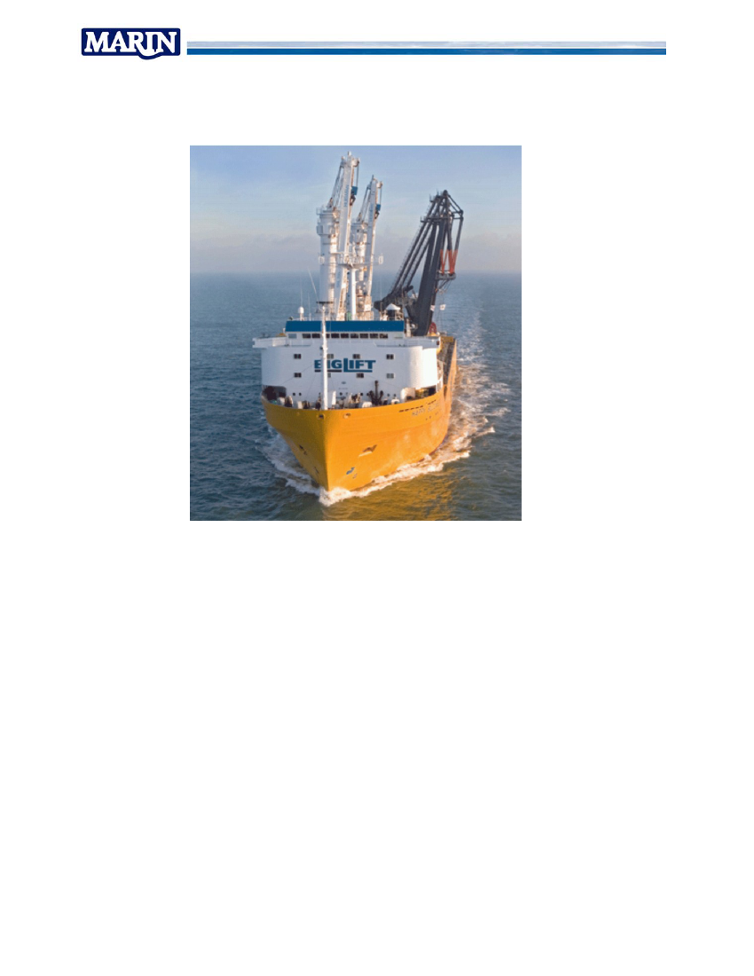
4.1.2.1 Heavy Lift transportBiglift Happy Buccaneer
Figure 1 Biglift Happy Buccanneer
The vessel sailed the Eastern hemisphere mainly between Persian Gulf, Far East andAustralia / New Zealand.Measured quantities included:•Vessel position, Speed and Heading;•Wave and wind data;•Forecasted wave and wind data;•Ships motion response and accelerations in two locations.Work was performed by MARIN with assistance and support of:•Biglift shipping both at main office for logistics, and crew on board during themeasurement period of two and a half years;•Amarcon for logging of forecast data and on board calculation of predicted motionresponse in the expected waves.
Report No. 19717-20-TM
12
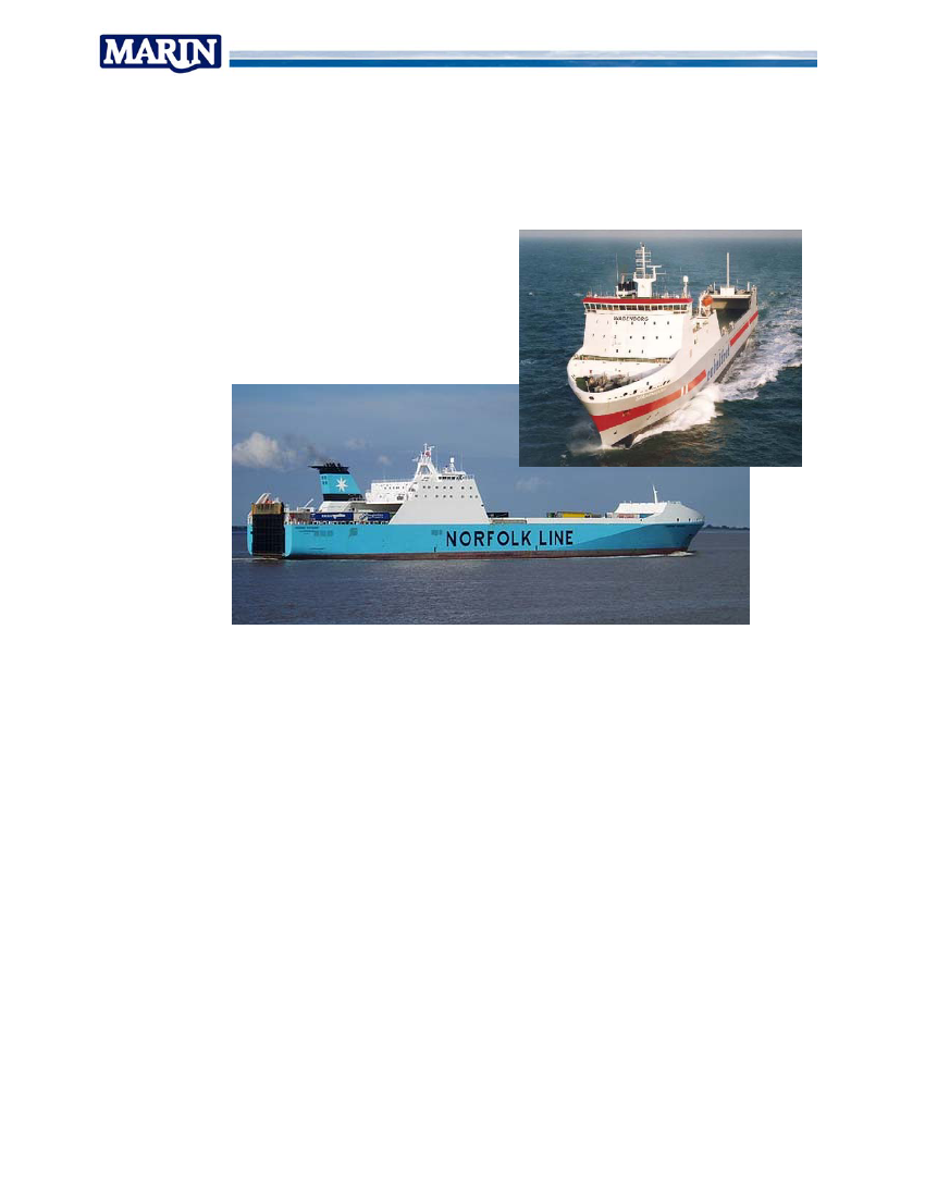
4.1.2.2 RoRo transport•Norfolk Line -Maersk Voyager•WagenborgSchieborg•MTIMCS facility
Hull response & lashing loadsHull response & lashing loadsLashing loads and cargo dynamics
Figure 2 Maersk Voyager & Wagenborg Schieborg
Measurements were performed on board the two vessels and included:•Motions of the vessel at two locations;•Position, speed and heading;•Forces in the cargo securing of one transport unit.Work was done by:•SIRI Marine for overall measurements in cooperation with•Norfolk line & Wagenborg for logistics and assistance by crews on board•Amarcon for logging of wave forecast climate (SPOS) and on line motion predictionsusing OCTOPUS software suite.
Reeport No. 197717-20-TM
13
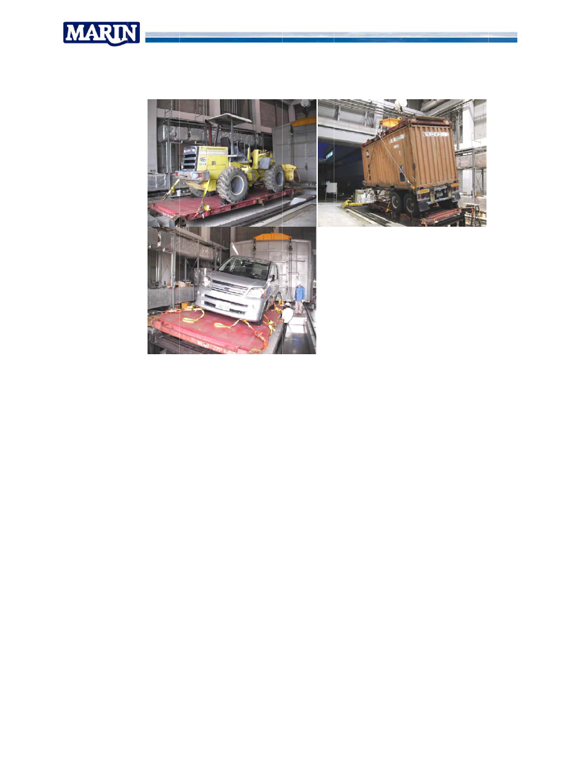
Figure 3 MCS tests for RoRo sectorrr
Work wa aimed at evaluation o design assasofsumptions fo cargo secuoruring system undercontrolle environme condition The MCS facility could be used t generate a clearedentns.Stodefined motion respoonse and corresponding acceleration field. Variou configurations ofusnitsgogear were evaaluated.cargo un and carg securing gMeasure parameters included:es•Platfo motions and acceleraormations;•Rollin cargo secngcondary motio and acceonselerations;•Lashing loads during the testss;•Video footage during tests.oasdWork wa performed by:•NYK / Monohakkobi Institute of technology who opeperate the MCS (multi cargouldsimulator) where the tests cou be conducted.Term who cooordinated the test preparration, execuution and repoorting, assist byted•MariT•Walleenius Wilhelmmsen who prrovided materials and enggineering suppport.•SEC who provide the lashing materials tha were used in the tests.eatd
Report No. 19717-20-TM
14
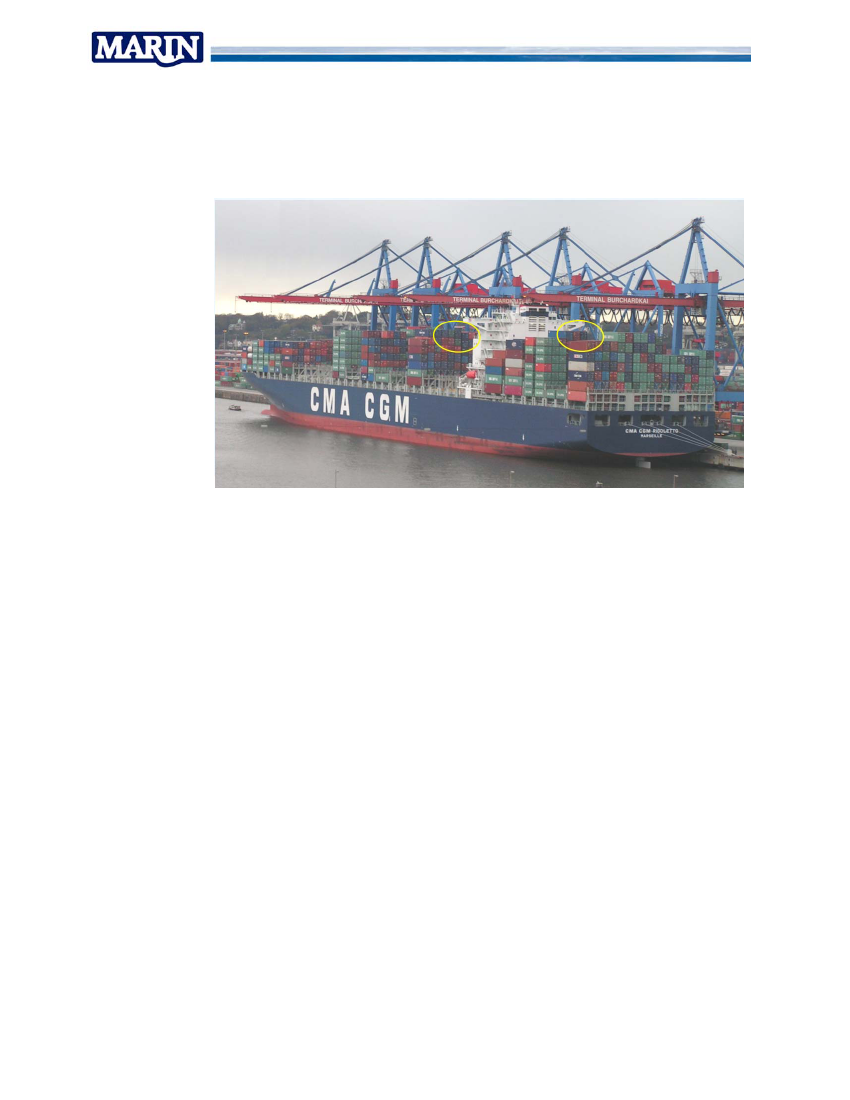
4.1.2.3 Container transportMeasurements were conducted on two ships and in the MCS test facility in Yokohama.4.1.2.3.1 CMA-CGM Rigoletto
Figure 4 CMA-CGM Rigoletto
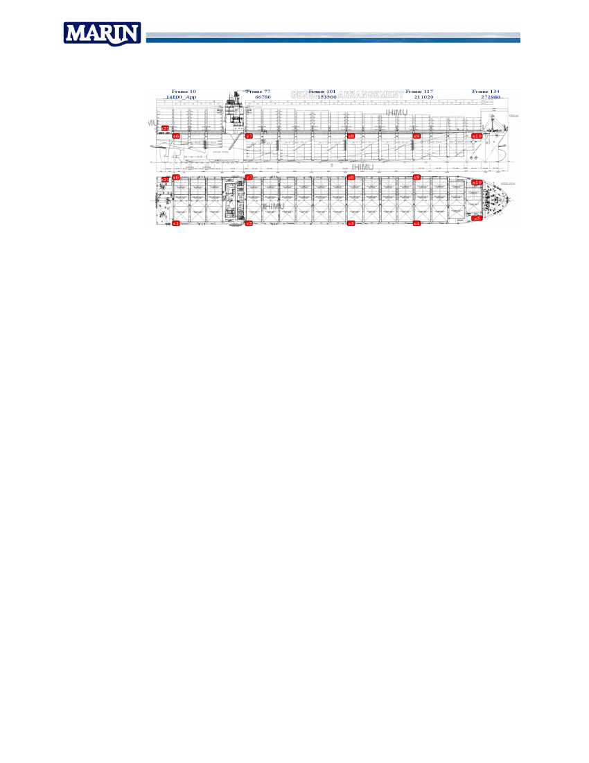
Work was aimed at identification of load contributions by hull accelerations anddeformations, and the response of the cargo stacks to these loads. For that purpose thevessel was fitted with following sensors:•a grid of 11 acceleration sensors along the length and width of the hull;•hull deformation and load sensors in two cross sections;•data link to obtain, position, heading, speed, rpm, rudder and wind data;•data link with loading computer and weather forecast data;•Instrumented container that was carried in top tiers of aft bay and first bay forward ofthe accommodation.The work was carried out by:•MARIN who had overall coordination and responsibility for instrumentation in the hull.•Bureau Veritas who handled the instrumentation and maintenance of theinstrumented container and•CMA CGM who provided logistics assistance to handle the container box, provide theslot to carry it for a period of two years and offer crew assistance with maintaininginstrumentation performance and data collection.•Amarcon who provided the OCTOPUS software that was used to interface with theloading computer and weather forecast module and provide on board calculation ofnotion response in forecasted weather.
Reeport No. 197717-20-TM
15
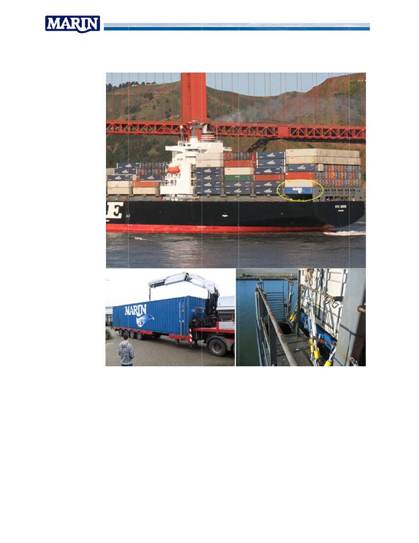
4.1.2.3.2 NYK Argus2
Figure 5 NYK Argus, MMARIN instrummented container & lashing rods
Work wwas aimed a identificatattion of load contributions by hull acceleration anddnsdeformaations, and th response of the cargo stacks to the loads. Fo that purpo theheeseorosevessel w fitted with following sewashensors:•A grid of 11 acceldleration senssors along the length and width of the hull;e•Hull deformation and load sendansors in two cross sectioncns;•Data link to obtain position, hn,heading, spee rpm, rudd and wind data;ed,derrta;•Data link weather forecast datumented conntainer that w carried in bottom tie of aft bay to record lawaserashing-•Instruand ccontainer staack- forces.
Report No. 19717-20-TM
16
Figure 6 NYK Argus - Accelerometer sensor grid
The work was carried out by:•MARIN who had overall coordination and responsibility for instrumentation in the hulland the instrumented container;•NYK line that provided logistics assistance to handle the container box, provide theslot to carry it for a period of one year and offer crew assistance with maintaininginstrumentation performance and data collection;•Amarcon who provided the OCTOPUS software that was used to interface with theloading condition and weather forecast module and provide on board calculation ofnotion response in forecasted weather.
Reeport No. 197717-20-TM
17
4.1.2.3.3 MCS test3ts
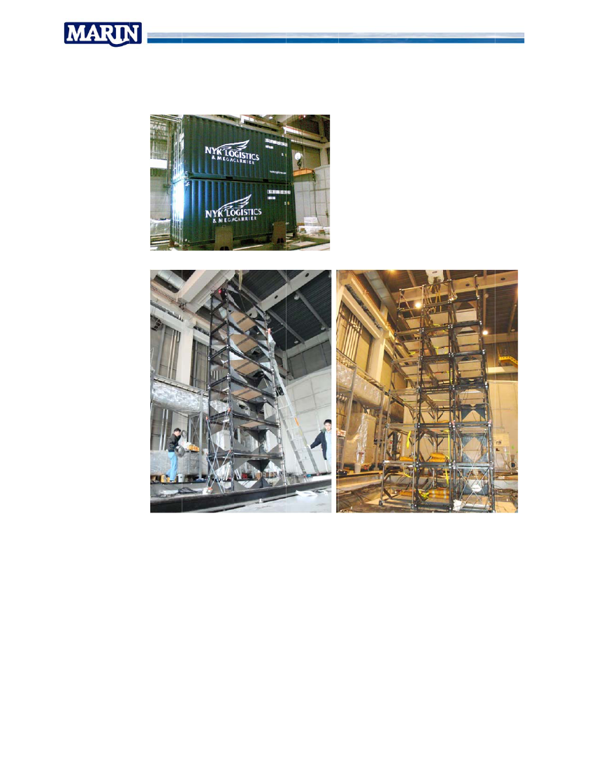
Figure 7 MCS - Full scale container tests 2 tiers
cale tests 2-7 tiers, 1-3 rowsFigure 8 MCS Model sc
wasessaviour of mulltiple tier and multiple row container stacksdwTarget w to addre the behaand to verify if lasshing loads and stack rresponse we in agreeereement with designassumptions.
Reeport No. 197717-20-TM
18
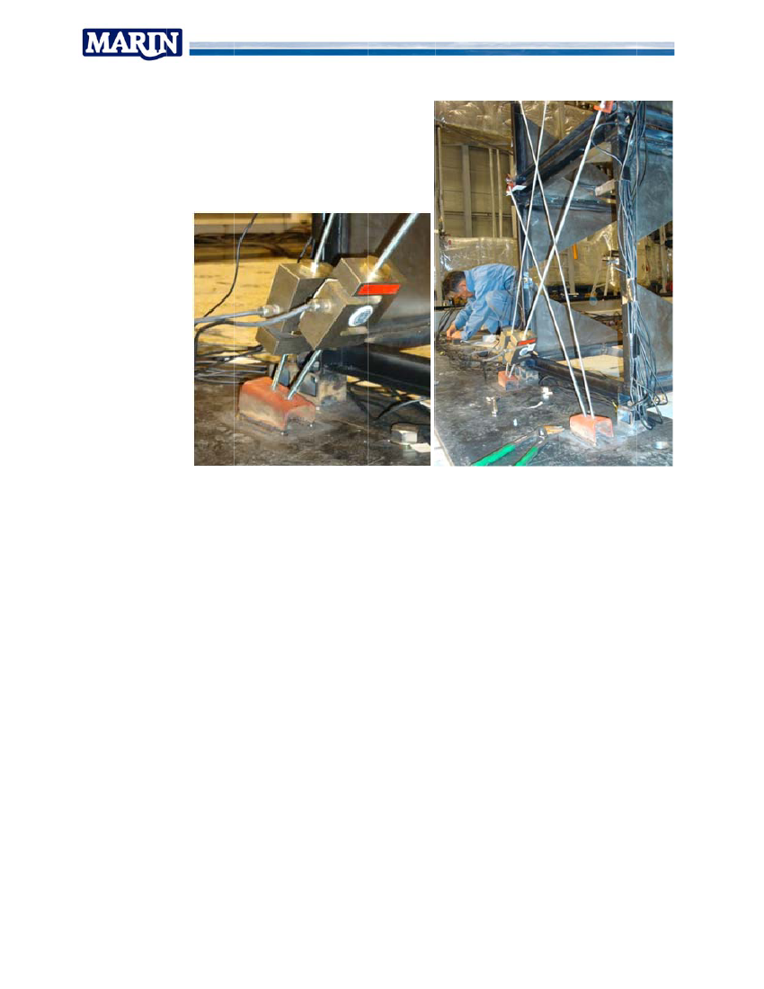
Figure 9 MCS - lashing instrumentatgtion
The insttrumentation included:•extennsive grid of accelerometers in the staaacks;•motio and acceonselerations of t test platftheform;•lashin forces;ng•Video footage.oasWork wa done by:•MAR for coordRINdination of overall test program, scaling proceduures, overloo theoksexecution of tests and data ansnalysis;tion of the teests in Japa andan•NYK / MTI who assisted in preparation and executcation of the container sccale models;fabric•Germmanischer Lloyd who deesigned a coontainer sca model to meet the scaledaleorequiirements for an actual 20 feet container unit;a•Univeersity of Tok who assisted in the execution of the tests and evaluation of thekyoemechhanical propeerties of the ffirst prototype of the conesntainer scale models.
Report No. 19717-20-TM
19
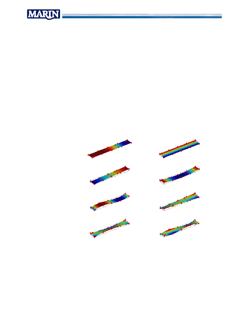
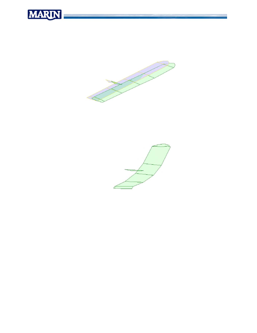
4.1.3 Data analysesData from measurements was analysed according to following procedures:•remove measurement spikes;•data reduction to obtain 30 minute statistics of measured signals;•checking for sensor integrity based on statistics;•Selection of interesting events;•Detailed evaluation of selected events for occurring phenomena, rigid body motions,hull deformation, whipping, springing, and torsion deformation in the hull;•correlation between deck, container and lashing responses;•Assessment of container stacks dynamics.A variety of tools and approaches was used and developed in the evaluation of themeasurement results.A spatial filtering algorithm was developed in order to isolate rigid body motions andflexible deformations from the combined measured signals of the 10 accelerometersalong the deck.
heave
roll
30020020 0-201000pitch50-520 0-202001000VBM 2nd
300
30050-520 0-200VBM 3nd20010050-520 0-200TRS 1nd200100
300
30050-520 0-200TRS 2nd20010050-520 0-200TRS 3nd200100
300
30050-520 0-20020010050-520 0-200200100
300
Figure 10 Hull deformation parameterisations
Dynamic mode analysis was applied in order to visualise and isolate natural modes andoperational mode shape deflections from the measured data.Selected results were compared with values obtained from design model assumptions inorder to assess the relevance of phenomena that were not included in thoseassumptions.
Report No. 19717-20-TM
20
4.1.4 Ranking of key factorsA series of key factors was identified in the course of the review of current practice andthe data analysis of the measurement data from the on board and MCS tests.These phenomena were ranked in order to produce a clear picture of the most importantaspects that determine safety and efficiency of sea transport for the various sectors.4.1.5 Definition of conclusions and recommendationsBased on the identified ranking of key factors, conclusions were drawn andrecommendations were formulated. Part of these was proactive and others werereactive. The proactive part addressed the factors before a vessel goes into operation orputs to sea with a particular cargo and lashing configuration. The reactive part aimed athandling the vessel while in transit in order to minimize the probability for incidents incase of unfavourable conditions.
Report No. 19717-20-TM
21
55.1
RESULTSReview of current practice
5.1.1 RulesMost important rules & guidelines for cargo securing practice are defined by SOLAS andIMO.•SOLAS § 5 Regulation 5: Standard cargo on ships should be secured using theprocedures and gear as described in the Cargo Securing Manual (CSM).•IMO – MSC circular 745 on Cargo Securing Manuals•IMO Code of Safe practice for Cargo Stowage and Securing (CSS code)Basic purpose of the cargo securing system is to prevent cargo from shifting.The IMO documents provide a framework for the requirements that the cargo securingsystem is supposed to meet.Flagstates are responsible for the practical interpretation of these rules and for theassessment and approval of the operational documents (CSM’s) that are offered by shipoperators.After meeting these requirements any design is expected to be fit for purpose. As suchgear is designed to meet rule requirement and not specifically to meet operationalconditions. Meeting the rule requirements is considered to implicitly mean thatoperational conditions are met as well.IMO Circular MSC/Circ.745 on Cargo Securing Manuals § 3.3.1 lists that followingfactors, among others, should be taken into account when the risk of cargo shifting isconsidered:- Duration of the voyage- Geographical area of the voyage- Sea conditions which may be expected- Expected static and dynamic forces during the voyageDesign conditions that are considered explicitly are•rigid body motions and accelerations by waves;•wind loads;•water sloshing loads if applicable;•internal forces from the cargo securing system.The CSS code Annex 13 tabulates acceleration values that should be used for thedesign process. Paragraph 7.1 states that for operation in a restricted area theaccelerations may be reduced taking into account the season of the year and theduration of the voyageThe code mentions that higher values could occur under conditions where non linearphenomena as parametric roll, dynamic loss of stability, wave slamming and hullwhipping are likely. These conditions should thus be avoided by the crew and as sucharenot partof the design envelope.•It was noted that no guidelines are given on how to include guidance in the CSM inorder to avoid excessive loads by non linear effects.•Also there is no reference on how the design reductions for restricted environmentalconditions should be included in the CSM.
Report No. 19717-20-TM
22
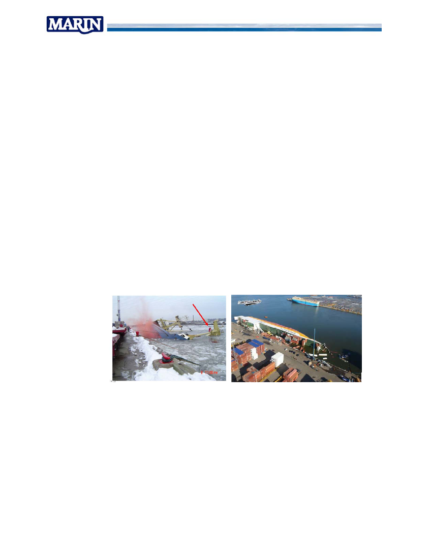
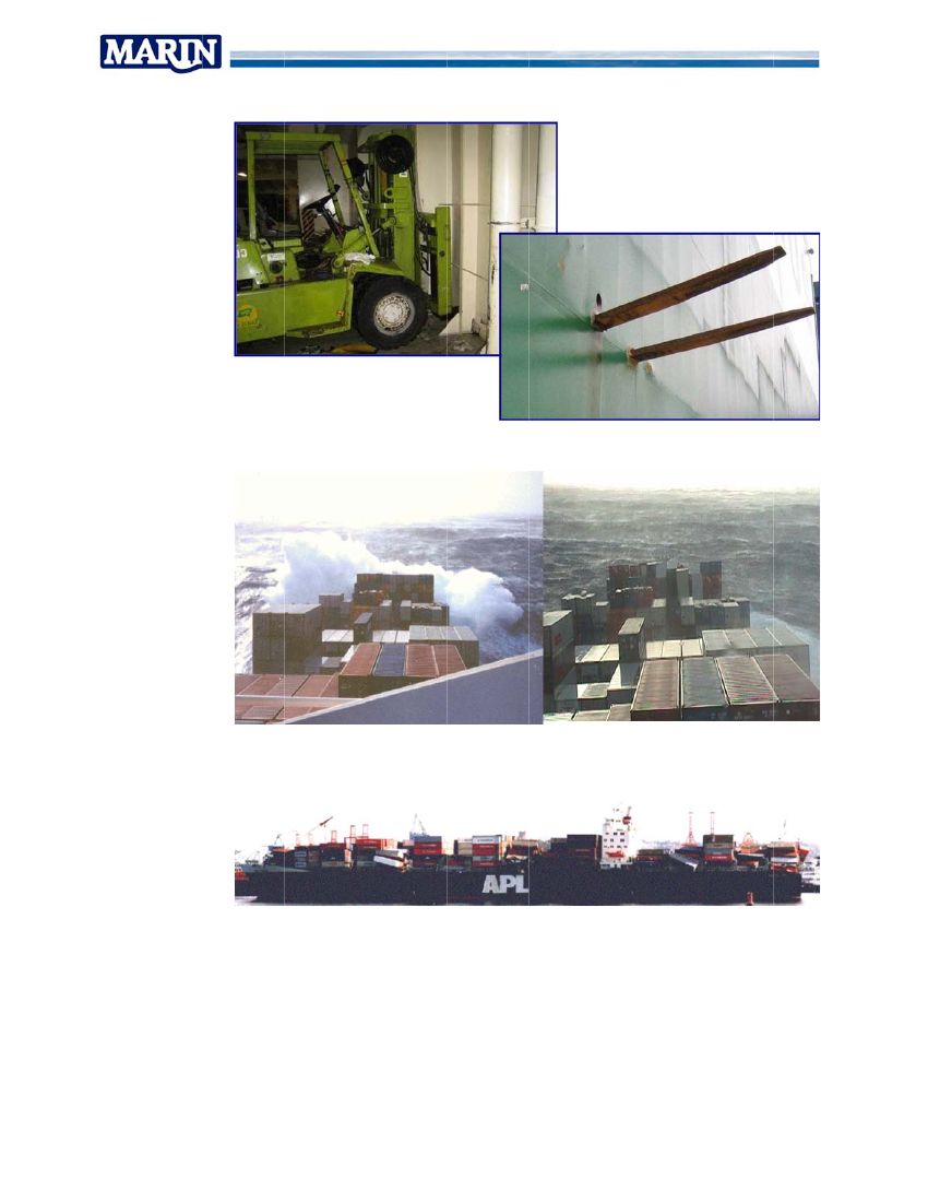
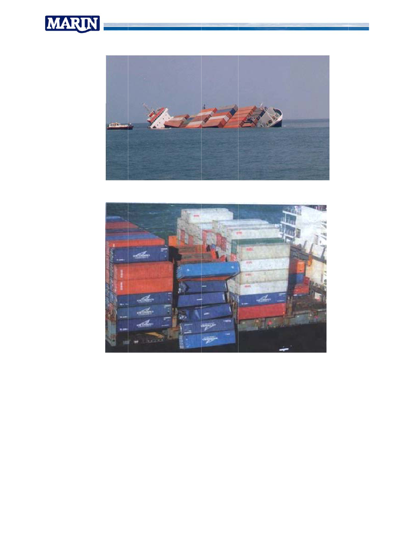
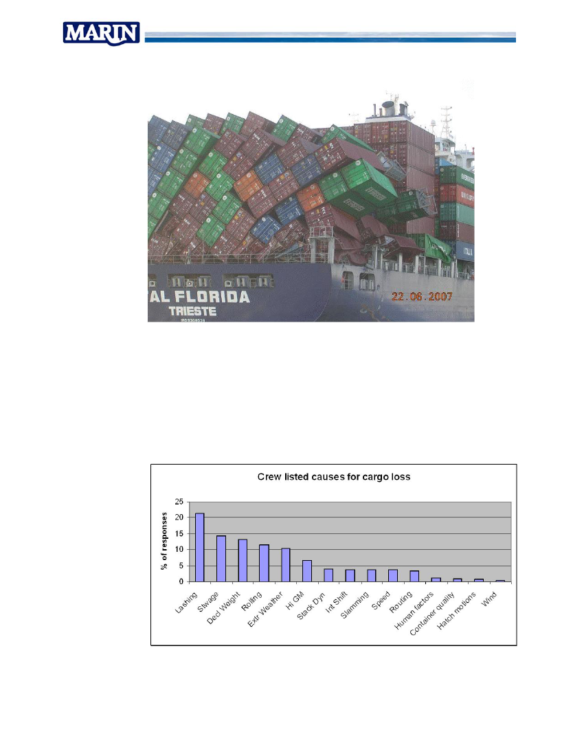
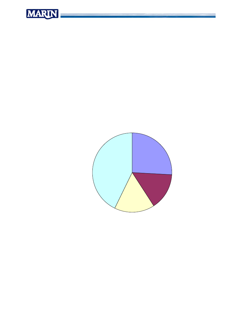
5.1.2 Typical incidentsTypical incidents relate to the accidents that may occur. The incidents indicate the typeof events that a cargo securing system should be expected to meet and shouldpreferably be designed to deal with.It was learned that no centralized data base is kept on shipping incidents relating tocargo loss and damages. Damage reports go from vessel to line operator, involved localmaritime authorities (coastguard) and P&I club. Line operators are held back to exposeincident details as it is bad publicity and since the P&I club are dealing with the matter.The P&I club investigate the details of the incidents but do not share findings. A reliableevaluation of trends in relation to innovations and scale enlargement can thus not bemade.Interviews with vessel operators, fleet managers, crews and stevedores provideinteresting information on incidents and near misses. They are however difficult to quotesince generally no details may be shared.The most interesting source of information then is the Internet where many reports ofmore or less “public released” incidents are shared on several sites and loose articles inlocal papers.It was found that there does not seem to be a single typical type of incident that can besaid to explain the majority of cases. Incidents occur along the quay, while leaving port,in head seas, beam seas and in following seas. Incidents occur in severe weather butalso in calm weather. This multitude of conditions suggests that a “silver bullet” solutionto solve the safety issue is unlikely to exist. A selection of incidents is highlighted inFigure 11 thru Figure 17 to illustrate the variety of conditions where accidents happened.
Figure 11 Incidents - In port during loading / offloading
Reeport No. 197717-20-TM
23
Figure 12 Incidents - C2Consequential damage by cargo shiftlc
Figure 13 Incidents - H3Head seas, hig speed -> bo damageghow
Figure 14 Incidents - H4Head seas, low speed -> parwrametric roll
Reeport No. 197717-20-TM
24
Figure 15 Incidents - lo GM / low fr5owreeboard
Figure 16 Incidents - U6Unexplained b collapse / ebayempty containersn
Report No. 19717-20-TM
25
Figure 17 Incidents - Unexplained bay collapse / loaded containers
5.1.3 Crew questionnaires container vesselsA crew questionnaire was assembled in order to obtain feedback from the operationalexperts on boards of containers ships. 158 responses were returned from vesselssailing for the ship operators in the project. The objective of the questionnaire was to listthe most relevant hazards for cargo securing on board and the concerns that contributeto decision making in the bridge. A selection of results is listed:The hazards for cargo securing as assembled from the crews responses are shown inFigure 18
Figure 18 Crew listed causes for cargo losses
Report No. 19717-20-TM
26
Of the total respondents 30 Percent was found to have experienced damaged or lostcontainer cargo. This seems a high percentage but it is in agreement with the estimateddamage probability of 0.05% for a transported container. The small percentageproduces a similar probability for incident when combing it with the large number ofcontainers on board in a single trip and the number of transits that average officers sailin their career.A review of the causes for the actual incidents that were returned produced followingshort list of factors:•handing the vessel in severe weather (speed, heading);•failing twist locks and deck fittings;•internal cargo shifting and•poor stowage (weight distribution) and declared weight.About the feasibility to determine when loads become too high and thus decide whenremedial actions are needed (speed, heading)Is it possible to get a good impression on the developing loads in the cargo securing’sfrom the bridge and react in time? Or can developing high loads go unnoticed?”
Yes
Not possible
Not from bridgebut from deck
Not alwaysObviously it is very difficult for vessel crews to get good feedback from the ship in orderto take timely actions to prevent excessive loads.Crew guidance for cargo securing is supposed to be described in the CSM. It wasreturned by 25 percent of the respondents that ships are regularly operated in conditionsoutside those described in the CSM. In this case typically the GM value is above themaximum value evaluated in the CSM. When sailing in part loaded condition, this cannot be avoided on many ships.
Report No. 19717-20-TM
27
5.1.4 Review of RoRo sectorThe RoRo sector was reported to endure most incidents by cargo securing that was notapplied according to requirements in combination with roll inducing effects as severeweather or even manoeuvring.In many occasions RoRo cargo securing is designed to lower standards than thoselisted in the IMO Code of Safe Practice for Cargo Securing and Stowage. Various flagstates have agreed/adopted procedures to evaluate and approve cargo securingprocedures for reduced environmental conditions. These are then added with the CargoSecuring Manual.No internationally agreed procedures exist to provide guidelines for this. This may leadto the development of a non level playing field and possible even to (unintentional)decrease of safety levels since no standards occur.It was proposed that internationally agreed guidance on dealing with this issue will:•Create the opportunity to maintain safety by evaluating requirement in wider context.•Assure a level playing field as all operators can apply to the same set of rules andrequirements.•IMO was listed as the most suitable body to carry such guidance. Classificationsocieties, joined in the IACS community, were however proposed as the best suitedplatform to develop and maintain such guidance. Their technical and more dynamicnature would allow considering all topics and agreeing on a working document to beoffered to the IMO council as an interpretation of standing IMO legislation.5.1.5 Review of Heavy lift sectorThe current practice in Heavy lift sector is relatively straight forward.
Choose ship & stowage plan
Design accelerations & loads
Evaluate deck loads
Design reinforcements & seafastenings
Draw out loading manuals andother documents
The key issue lies in the required approval of the final documents by warranty surveyors.No clear guidance on the requirement for design accelerations and loads is available.
Report No. 19717-20-TM
28
Various values are offered (e.g. by class, design software codes, IMO). Often there isdiscussion on what design values should be used. This results in delays and extra costswhen further reinforcements and sea fastenings must be fitted.The in service practice learns that incidents in transit are rare. The vessel crews areexperienced mariners; most significant loads are induced by rolling and pitchingmotions. By controlling speed, heading and ballasting condition, these loads areconsidered to be well under control in the expected sea states. Routing plans areroutinely laid out to avoid severe weather if sensitive cargo is mounted. Vessel control isbased on crew impression of rolling motions, and probability of wave slamming in headsea conditions.Main challenge for Heavy Lift sector is to increase acceptance of design procedures thatare in use for past years and that seem to perform well as indicated by the goodperformance of the fleet.5.2Measurement campaigns & Data analysis
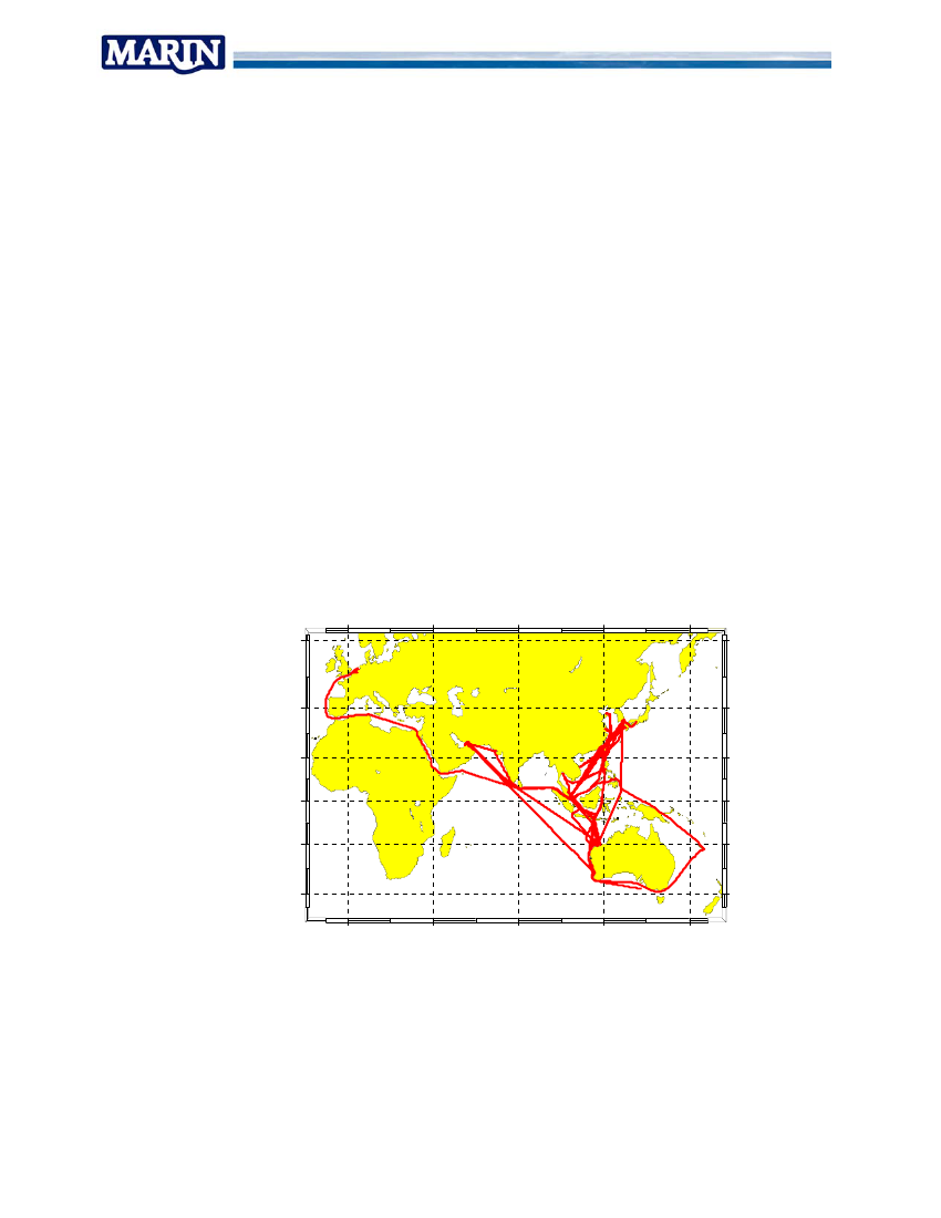
5.2.1 Heavy Lift transportBuccaneer measurement data spans the period from December 2006 until May 2009. Inthat period she sailed from Europe to the Far East where she stayed and sailed variouscargos between the Persian Gulf, Australia and the Far East.Buccaneer#000 : 2006-2009AllData
60oN
40oN20oN0o20oS40oS0o40oE80oE120oE160oE
Figure 19 Sailed track Biglift Buccaneer
It was learned that motion climate seems to be actively limited to rolling motions ofaround 15 degrees and pitching motions up to 7 degrees single amplitude. The majorityof time operations are in not too severe weather. Maximum sea states up to 9 meters
Report No. 19717-20-TM
29
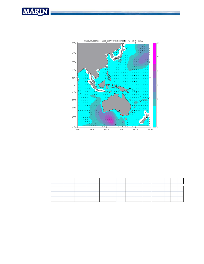
significant wave height however were recorded using the Wave Radar sensor in thebow. Typically Buccaneer successfully evaded the worst parts of forecasted weather.
Figure 20 Buccaneer evading severe Southern Ocean storm
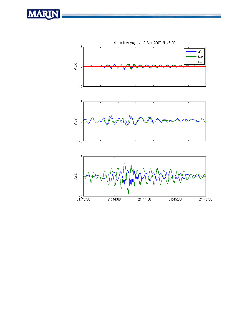
It was found that acceleration loads in the cargo area, were dominated by transverseand vertical accelerations. Transverse accelerations were highest in combination withrolling motions due to earth gravity contribution. Vertical accelerations were highest byheave and pitching motions. No significant slamming loads were found in the recordingsof accelerations.Highest responses were recorded as follows:DepartureDestinationTODTOAextremeWindspeedknt305030303525Hsrdr[m]xx10465Hsnoaa[m]5443.54.5Mariners Hvehandbook[m]5955‐663‐4[m]4.53.533.52.53RllPtcAcYAcZ
BaiedeProny FremantleDampierSingaporeFujairahKwinanaBatamIslandZhangzhouDampierShanghaiNantongFremantle
2/13/20073/4/20079/24/200712/31/20071/25/20084/22/2008
2/22/20073/12/200710/11/20071/7/20082/5/20085/4/2008
2007‐02‐19th2007‐03‐7/9th2007‐10‐7/10th2008/01/1‐2nd2008/05/03rd
[deg] [deg] [m/s^2][m/s^2]1053.531573.531543315343361411332
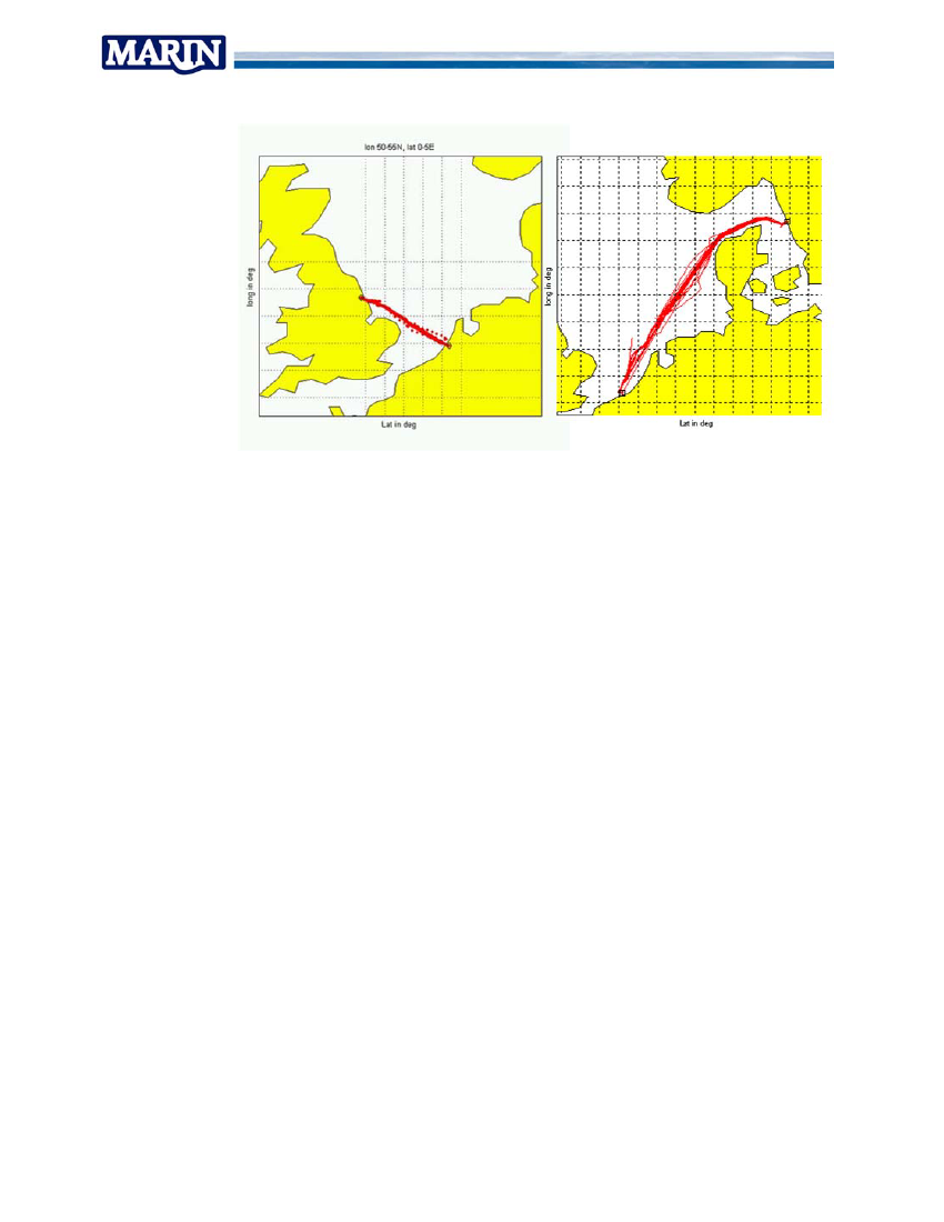
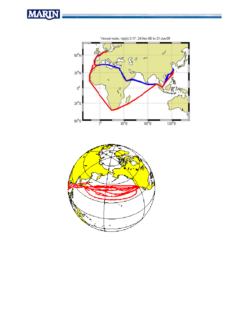
5.2.2 RoRo vesselsMeasurements on board Ms Schieborg and Maersk Voyager lasted from begin 2007until mid 2008. Vessels were trading the North Sea, German Bight and Skagerrak asshown in route maps of both vessels.
Report No. 19717-20-TM
30
Figure 21 Sailed tracks mv Maersk Voyager/ mv Schieborg
The measurements on board the RoRo vessels resulted in similar findings as the resultsfrom the Heavy Lift campaign. Highest measured accelerations added to 4 meters/s^2 intransverse direction and 3-4 meters/s^2 in vertical direction. Although some slammingloads were identified in the data it was concluded that rigid body motions dominate theacceleration loads that are imposed on the cargo. Hull deflections and short durationimpact phenomena are of smaller importance.
Report No. 19717-20-TM
31
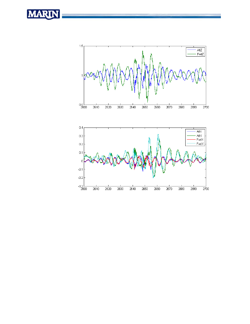
Figure 22 Measured g-loads in transit Schieborg
Report No. 19717-20-TM
32
Figure 23 Measured accelerations Maersk Voyager [m/s^2]
Lashing Forces were observed both on Schieborg and Voyager and learned that loadsare related to the rigid body motions mainly. Pretension levels in the lashings wasobserved to be around 10-15 KN on average or 1 to 1.5 tons. Upon progress of thetransit the pretension levels were observed to reduce. Dynamic loads variations aroundthe mean pretension levels were observed to approach the pretension level potentiallycausing lashings to fall slack.It was observed that max lashing force does not solely rely on vessel accelerations. Themass and rigidity of the secured trailer naturally plays an important role as well. Thesewere however not logged.
Report No. 19717-20-TM
33
Figure 24 Typical web lashing force recordings [KN]
5.2.3 Container vesselsThe container ship measurements clarified several aspect of in service loads on board.The loads experienced by the vessel depend greatly on the trading route. The vesselsinvolved in the measurements traded Europe - Far East (Figure 25) and Far East – USwest coast (Figure 26).Rigoletto clearly does not take many actions to avoid severe weather. From one side herroute does not give many options to alter course. Sailed distances in vicinity of severeweather areas are short. On the other hand there are not many heavy weather areasalong its path. The Gulf of Biscay is renowned and does not provide options to changecourse and evade weather. In the Far East choices to pass Taiwan to port or starboardin typhoon season provide options to select most favourable route.NYK Argus on the other hand is crossing the North Pacific twice in her two month roundtrip. The variation in the sailed tracks reveals the efforts taken by the crew to avoid worstdepressions and wave fields.
Reeport No. 197717-20-TM
34
Figure 25 Trade route Rigoletto (plu trip around cape avoiding Suez and So5usgomalia)
Figure 26 Trade route NYK Argus an weather av6ndvoidance
Measureements on bo vessels learned that accelerations to the cargo are compoothsosed ofa rigid body motion part and contributions by hull flensexibility. The hull structueures incombinaation with cargo weights have lead to hull natural frequency f vertical bendingolforof 0.5Hz or 2 secon periods. This is close to the excitation loads by waves in headzndsenseas.
Report No. 19717-20-TM
35
Following cases are recognised from the measurements:•Highest transverse loads are occurring in rolling motions by contribution of earthgravity. Rolling motions of 15-20 degrees single amplitude are common in followingseas.
Figure 27 Acceleration pattern along hull in rolling motions
•Highest vertical loads are occurring in head sea conditions by combination of heave,pitching and vertical hull bending.
Figure 28 Acceleration pattern along hull in head seas
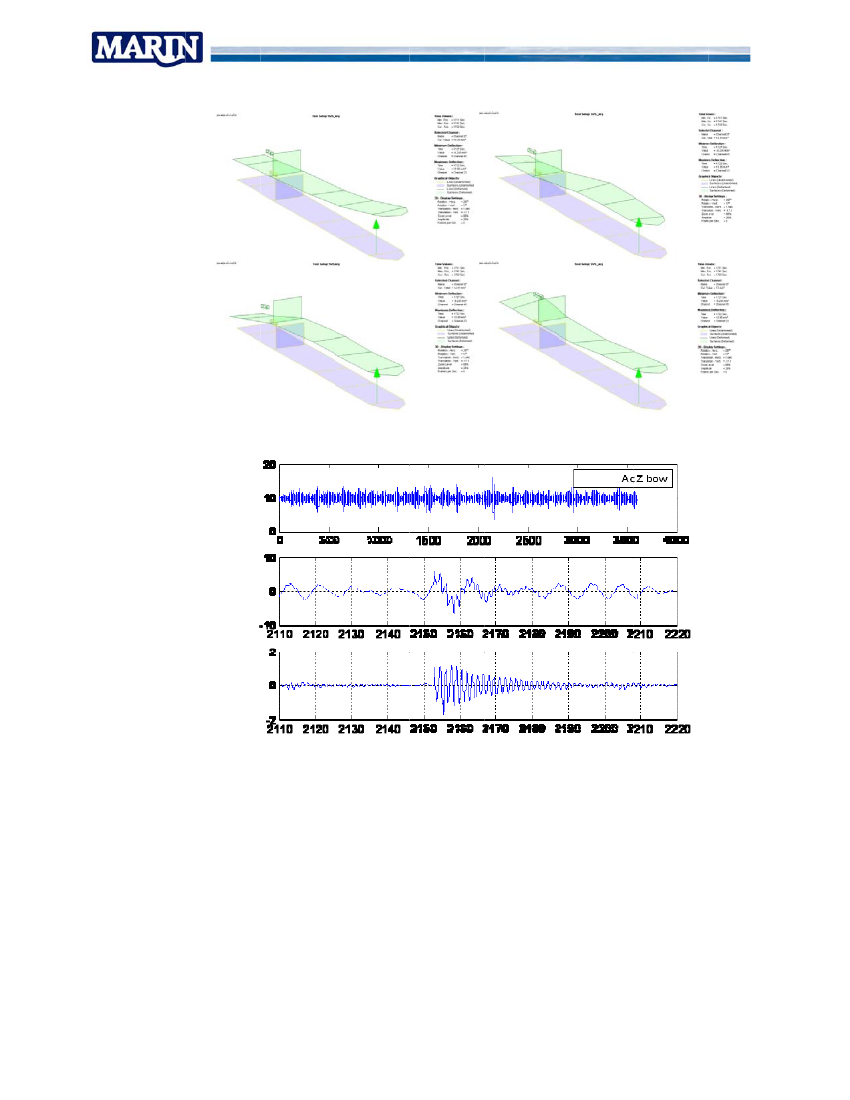
•Flexible hull deformation is adding around 40-50% to the accelerations that couldotherwise be expected based on rigid body motions alone.•The highest loads occur due to wave slamming. This induces an impulsive load thatis super imposed over the peak acceleration by heave and pitch.•The effect of a wave slam is experienced in the aft ship as well. The impact passesthrough the hull as a travelling wave and when reaching the light and flexible aftstructure results in a peak acceleration of similar amplitude as the original slam in thebow.
Reeport No. 197717-20-TM
36
Figure 29 Wave impac (read left to right, top first9ctt)
Figure 30 Peak acceleration and dec (1 hr, zoom0caymed, and flex. part only)
knsortly after the impact. Deeecay of the impulsive ressponse•Peak acceleration occur shotakes around 30 seconds.ss•Maximum accelerations to 6 mm/s^2 were recorded in bbow quartering seas. Bow flarewected to pose the largest threat for wetwave impulsiv loads. Bow flarevewslamming is expeybow quartering head seas.slamming is likely to occur in b
Report No. 19717-20-TM
37
•Hull deformations occur due to encountered direct wave loads and due to dynamicresponse in the hull natural frequency.•The main phenomenon that is contributing to extra accelerations is the verticalbending of the hull in its natural frequency mode. No significant contribution of torsiondeformation was observed in the measured accelerations. It is assumed that this iscaused by damping from row-row interaction in the container stows and by the smalllever arm and torsion deformation angles.•Torsion as well as bending was observed due to direct wave loads. Torsion showedcontributions from rolling motions and wave encounter periods. Vertical bendingmainly comprised of wave encounter frequency contributions.•It was observed that cargo hatches may shift in the order of 2 cm due to verticalbending. No relation with torsion deformation could be obtained from themeasurements.•Measurements in the container stow on board NYK Argus and CMA-CGM Rigolettolearned that dynamic effects in the stacks may be expected when excitation loadshave short periods. This occurs typically in head waves and in wave slammingevents.•Highest container stack accelerations however were observed in following seas.These were found to behave very linear and following the expected loads from thevessel closely.•Highest dynamic loads were observed following a wave slamming event on thePacific. Measured responses suggested row interaction must have occurred as highforces and g-loads were measured while no heavy boxes were carried in the stack atthe time.
Report No. 19717-20-TM
38
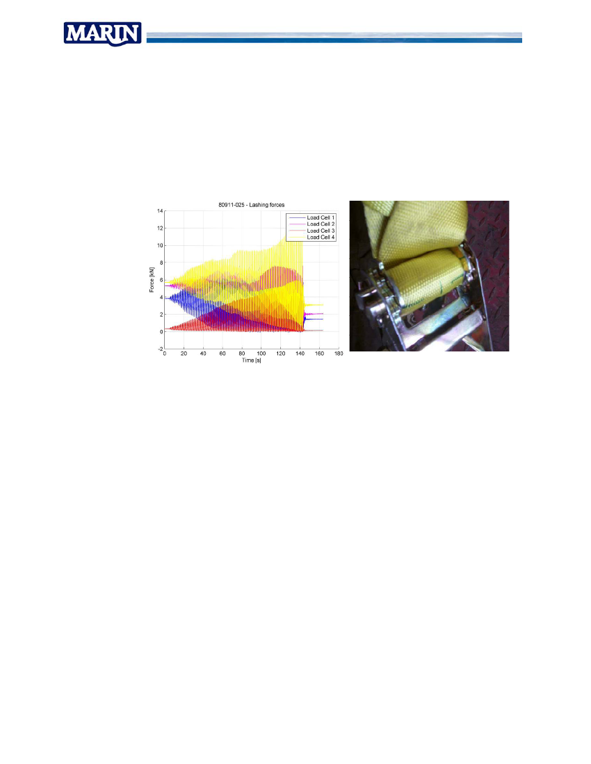
5.3 MCS testsMCS tests were aimed at behaviour of RoRo cargo under dynamic loads and thedynamics of container cargo in single- and multiple- row configurations. Followingresults were obtained.5.3.1 RoRo tests•The lashing pretension was observed to slacken off during the tests both for chainand web lashings. With the web lashings it was observed that the straps werecreeping out of the ratchets under repeated loads.
Figure 31 Lashing forces and ratchet windings
••••
••
It was noted that practical aspects determine the reliability of how the lashings areapplied and how pretension is distributed.No snapping loads or unhooking was observed in the tests.Cross lashings did not add to tipping stabilityThe obtained results generally agreed with the calculation methods. On someoccasions the distribution of loads over the applied lashings exceeded the safetymargin of 1.35 that is used in the CSS model.A tendency was found that loads become more evenly distributed at higher loads.Cargoes with large own moment of inertia were found to increase the lashing loadsunder short periods movements (rotations).
Report No. 19717-20-TM
39
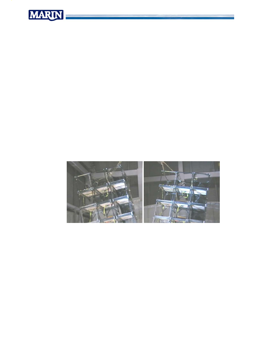
5.3.2 Container tests•Racking deformations determine the deformation and reaction forces at lowerexcitation levels.•At higher excitation levels uplifting occurs and the deflections are dominated bylimited tipping of the stack as allowed by the vertical gap tolerance in the twist locks.•There is strong coupling between transverse swaying of the stack and twistingaround the vertical axis due to the different racking stiffness forward and aft.•Modal analysis showed only one dominant deformation mode shape. Higher ordermode shapes are close to critically dampened by non linear interaction between tiers.(slipping, uplifting)•Test results indicate that natural periods of the higher stacks can approach 1 second.With extreme weight distributions it may further approach the hull natural period forbending and torsion making stacks sensitive to resonant loads.•It was calculated and observed that uplifting may be expected to occur at operationalheeling angles with stack heights of 7 tiers.•Configurations with multiple rows exhibit a stabilizing effect to general motionresponse when all stacks have similar mass and rigidity and move in sync. Theinteraction and friction between the rows introduces damping.•Responsive behaviour changes in case of rows with different mass or rigidity (failedlashings). Gaps may open up between the rows in particular direction as moreflexible or heavy rows tend to deflect further then the more rigid or light stacks. Rowsno longer move in sync and impacts can occur when gaps close up again.
gap
•Peak loads are introduced by impacts when the gaps close due to motions inopposite direction. The more rigid of light stack is found to exhibit peak loads that arefactors 2 - 3 higher than the expected values.
Report No. 19717-20-TM
40
5.4 Ranking of key factorsFollowing paragraphs discuss the findings in the previous stages and their relevance.Obvious considerations for the reliability and thus safety of the cargo securing systemare determined by:•Quality of the underlying design assumptions in relation to true physics;•Conformity of the on board situation with designed configuration;•Ability of the crew to keep service loads inside design envelope;The findings with the various transport sectors are listed as follows:5.4.1 Design model assumptions vs. actual physicsThis paragraph reviews if the fundamental assumptions that are the basis of the designrules and standards match the in service behaviour. Findings are grouped foracceleration loads on the stowed cargo, and secondary reaction forces induced in thesecured cargo.•Underlying design assumptions for RoRo and Heavy lift transport acceleration loadsmatch with actual response of vessels to wind and waves as rigid bodies.•It is considered possible to predict “linear” vessel response and cargo securing loadsto known wave climates.•Determination of the design wave regime / operational profile, and the maximumaccelerations in response to that is thus essential.•For container ships it was found that accelerations due to flexible hull deformationadd substantially to the “classic” rigid body design accelerations.•IMO guidelines do not consider contributions by “non linear” loads such asparametric roll, broaching, dynamic loss of stability and slamming to be a part of thedesign envelope. These are to be avoided by the crew. Various incidents howeversuggest that these effects do occur and as such contribute to actual service loads.•Reaction forces in lashing systems on the (smaller) RoRos and Heavy Lift vesselsdepend mainly on normal wave induced ship motions.•Force- and cargo shift- calculation procedures for RoRo trailers should addressbehaviour of forward and aft end separately•For large cargo items, the own moment of inertia should be considered since it canincrease tipping loads compared to the classic approach.•Shifting cargo due to reduced cargo securing may affect the survivability of a vesselin the case of an extreme event as a collision. It should be considered to includesuch an event in the design assessment of the cargo securing system.•Reaction forces and motions in container cargo are not merely in response to thelinear loads imposed by the vessel. Interaction forces between adjacent stacks werefound to have a big effect on resulting forces in lashings and container stow.•These effects may be expected to occur typically when rows are less stable due tofailing lashings or poor vertical weight distribution. As a result they will lean into otherstacks or open up gaps. The reaction forces across a bay thus are sensitive todeficiencies in separate single container rows.
Report No. 19717-20-TM
41
5.4.2 Conformity “design” and “in service” conditionsIn service cargo securing is carried out using the procedures and cargo gears asdesigned using current industry assumptions. Differences between the designed cargostow and the actual on board “in service” configuration are however likely to occur.•Most often recurring incident on RoRo vessels relates to shifting cargo insidetransport modules. This may trigger further cargo shifting and ultimately affect thesafety of the ship. Although this falls under the responsibility of the crew, the mastercannot practically be held responsible for this.•Integrity of the lashing system. The state of maintenance, wear and tear of loose andfixed lashing gear is of primary importance to the reliability of the securingarrangement. Although the majority of gear is in good condition, crew and accidentreports indicate that these factors contribute to incidents.•Properly fitted lashing gear is essential to cargo securing integrity. RoRo findingspointed out that not following CSM prescribed procedures played a factor in manyincidents. Findings on container stack dynamics also point out the relevance to haveall individual stacks properly secured according to the CSM.•It was observed that pretension levels decrease over the course of a transit. In RoRotransport slipping of web lashings from ratchets and equalizing of load distributionbetween chain lashings. Container lashings can lose pretension by loosening ofturnbuckles and/or setting of the container stacks. It must be noted that survey andretightening of cargo securing is often not possible in severe weather as decks aretoo hazardous for access.•The design of stacked cargo securing on container vessels is based on the weightsof the containers and the vertical distribution of these weights in the stack. It is notmandatory to weigh containers. Both actual weight and vertical weight distribution inthe stacks are not reliable and introduce uncertainty and potential hazard.•Design documentation is outlined for a limited number of vessel conditions. Partlyloaded conditions with extreme GM are often not included in these cases. The highaccelerations in beam seas may overload container stacks.5.4.3 Crew ability to keep loads inside design envelopeSafety issues are stressed by sailing into extreme weather. This is the design case forcargo securing. In practice it occurs only on a limited number of occasions. In theseoccasions the condition of the securing system as well as the loading configurationshould be inside the limits of the design assumptions (see above listed factors). Startingfrom that point further safety is in the hands of the crew under good seamanship. Forthat conditions following further considerations were identified.•Crews are usually able to control vessel motions by changing heading, speed andselecting appropriate ballast condition. Sometimes however uncomfortable vesselmotions and accelerations are noted to occur.•There may be limited options to set appropriate GM in order to avoid large transverseaccelerations by resonant rolling in partly loaded conditions.•Although it is expected from bridge crews to avoid the occurrence of extreme loads, amajority of crews indicates that it is hard to judge if loads are actually becomingunacceptable and when it is time to change speed/heading or other.•Non linear events as slamming, green water, parametric roll and dynamic loss ofstability in following seas need to occur first before action can be taken. (Eggchanging speed, heading). The first occurrences could however already be severe.Guidance for these conditions is often missing from the CSM
Report No. 19717-20-TM
42
5.5
Conclusions & recommendations
RoRo•IMO / SOLAS legislation allow cargo securing based on design accelerations inrestricted environmental conditions.•SOLAS requires that securing procedure should be in agreement with CSMdocumentation. This implies that cargo securing for limited environmental conditionsshould be described in the CSM and should be evaluated and approved by the flagstate.•Guidance as to how this should be done is missing. This guidance should bedeveloped and agreed / accepted at IMO level in order to create a level playing fieldand maintain a controlled safety level.•The agreement between design physics and onboard measured responses indicatesthat existing tools and approaches can be used to evaluate required guidance.•Such guidelines would typically be a dynamic working document prone to changes inresponse to new design concepts. It is proposed that a technical body such as IACS(International Association of Classification Societies) would be best suited to maintainsuch a document and recommend an accepted interpretation to the IMO council.•The Lashing@Sea project has drawn up a document for such an interpretation andhas asked IACS to consider the formation of a working group to take developmentfurther with focus on and recommendations for:oRequirements for tools used to consider environmental factorsoHow to evaluate the survivability of the vessel in case of reduced lashingoUnified requirements for lashing arrangementsoHow to combine various contributions to design accelerationsoGuidance on the condition of cargo transport units themselvesHeavy Lift transportThe challenges in the Heavy Lift transport sector mainly related to the interaction withwarranty surveyors for approval of each single transport design. The design proceduresare not standardized and give rise to different interpretation.Evaluations of 3 years measured data on Biglift transports illustrated that design valueswith class accepted probability levels could be based on local environment withexposure time of typically 10 times the voyage duration. This procedure has to beapproved by surveyors for each new transport and will likely keep raising discussion.It is proposed to follow approach similar to that with the approval of CSM’s for RoRocargo and have the general design procedures and the tools used, documented in theCSM for approval by the flag state. Reference should be made to the same guidelinesas these formulated for the RoRo industry. The actual design of the securingarrangement for each trip should then be done in accordance to the describedprocedures.The discussion with warranty surveyor about the followed engineering process andassumptions is then illustrated by the vessel specific procedures as approved by flagstate -and most likely class society- in the CSM.Container transportThere is a perception that container transport is troubled by unacceptably large losses.This was found to be hard to determine as no centralised databases are kept withregards to losses and details on incidents are typically unavailable. Because of this
Report No. 19717-20-TM
43
there is also no means to evaluate for systematic trends in incidents or returning triggersfor incidents. It was however clear that the unexplained losses of entire bays in recentyears need to be explained.Several aspects of in service conditions were found to be not explicitly included in theprinciples of the existing rules and standards. The most important ones are:•Increased accelerations due to flexible hull deformations (whipping/springing). Theseare observed to be occurring regularly in severe head seas.•Multiplication of the expected forces in cargo stacks due to interactions betweenadjacent rows. This effect occurs if gaps can open up between adjacent stacksallowing impacts when stacks sway sideways. This mechanism concentrates inertialoads on the most rigid row.Dynamic tests with multiple rows indicated that extreme loads are not expected whensecuring arrangement is in agreement with the design and no gaps open up. It washowever found that the system is sensitive to off design conditions, Dynamic loadamplifications up to a factor 2 to 3 were found in these cases. This indicates the need ofcompliance between designed and actual stow configuration.Interaction forces are considered to be the most likely reason for progressive collapse ofmultiple rows when due to a combined occurrence of events one or more stacksbecome unstable.Commonly known effects that add to stack instability and increase excitation loads are:•Poor deck fittings and twist locks have a bad effect on stack stability. Incidents learnthat damages and corrosion can go unnoticed;•Wrong applied lashings;•Lashings often loosen up and need to be re-tightened. This is done in daily routinesurveys (Which is not possible when the weather becomes severe);•Container weights are the basis of reliable stow design. The weights however areestimated and are not reliable;•The stow sequence and thus vertical weight distribution is often different from thestow plan. Crews mention this occurs regularly depending on port of call. If heavyboxes are stowed higher in the stack, the forces in lower tiers can exceed designlimits and stacks may become unstable;•High transverse accelerations in off design loading conditions (e.g. extreme GM)may raise excessive loads that loosen up/damage securing of highly loaded stacks,poor lashing gear or bottom tier container integrity;•Crew questionnaire findings showed that it is hard to recognize when loads becometoo high and decide when and what measures are needed to keep it inside safeworking limits.Loads that in itself are already hard to recognize for crews, may become higher thananticipated due to stack interactions, triggered by fairly simple phenomena.In order to reduce probability of incidents following recommendations are listed:Increase integrity of actual stows in relation to the CSM and stow planThe low incident probability for container transport illustrates that container industry is inprincipal fairly safe. Lashing@Sea investigations also did not reveal extra ordinaryfindings in either full scale measurements or in the MCS model tests with setupaccording to the design assumptions.
Report No. 19717-20-TM
44
The largest effect to substantially increase loads was found to be out off designconditions that are known to occur in service on occasion. (I.e. Overweight/instablerows by weight errors, poor gears, damaged containers). Based on this finding it isrecommended to reduce probability for these cases.•It is essential that gear is in good condition. Fixed lashing gears in particular arehard to check and may wear out unnoticed.•It is essential to have good agreement between the actual stow and the preliminarystow plan that is assessed and approved by the crew. It is noted though that cargo isstowed different from the plan on occasion.Procedures for this are already in place. To bring down the last fraction of percentagewhere incidents still occur, it is essential to make sure that things are also done inagreement to these standing procedures. Since the start of the Lashing@Sea projectseveral things have already happened:•An international standard for logistics responsibilities has been laid out in the“Rotterdam Rules”.•The international chamber of shipping (ICS) has addressed a recommendedpractice for container transport. “Safe transport of containers by sea, guidelines andbest practices”.To increase safety further it should be endorsed that best practices are actually followedand responsibilities are indeed taken where they should. Following suggestions arelisted:•Weigh container trailers upon entry/exit of the terminal to use the measured massfor stow planning. -> Remove mass uncertainty from process.•Random surveys to evaluate if stow and lashing procedures are properly followedwith feedback to responsible party -> better vertical weight distribution.•Harmonize maintenance standards of lashing gear and fixed fittings. For instance byincluding it in the annual hull surveys by class.•Design and make of lashing gear to be such that it does not loosen up in transit.Avoid excessive ship motions and accelerationsCrews should be assisted to improve the “feel” and “awareness” of loads outside thefield of view from the bridge. This includes the effect of sailing in off design stabilityunder high GM and evaluation of stack loads under these conditions. This should forinstance be described in CSM, and/or supported by loading computer lashing modulesor monitoring systems.Training, guidance or tools to reduce the chances for extreme loads by “non lineareffects” are a second step to be considered. Probability for extreme loads byunexpected resonant roll, wave slamming, parametric roll and dynamic loss of stabilitymay thus be reduced.The in service measurements demonstrated the possibility to measure loads andresponses. It is a big challenge to provide such info to crews in simple format.Review design standards and rulesIt has been found that non-linear responses may have an impact on determining thecriteria required to ensure the safe stowage of containers during some voyages.However, it is recognized that at this time, due to the vagueness and uncertainty of suchfactors, it would be an extremely difficult task to immediately prescribe criteria to accountfor these phenomena. The members of the industry whose task is setting design criteria(Administrations, Standards Institutes and Class Societies) are encouraged toinvestigate these aspects further, in order to increase the awareness and understandingof these findings
Report No. 19717-20-TM
45
6
EXTENDED SUMMARY AND CONCLUSIONS
The Lashing@Sea project ran from the period of mid 2006 through mid 2009. Itaddressed safety and efficiency for container ships, RoRo ships and Heavy lift transportships.The main scope of work addressed the validation of design assumptions by means offull scale measurements, review of current practice and extensive evaluation of findingsby a group of stakeholders that was brought together for the project.The stakeholders that were directly involved in the project included ship owners, lashinggear manufacturers, classifications societies, on board systems suppliers, technologyinstitutes and flag state authorities. Stevedores contributed by interviews. P&I clubs didnot participate.Measurements were conducted on two RoRo ships, two container vessels and oneHeavy lift transport ship for a period of more than two years. Ship motions, lashingforces, container forces environmental parameters and loading conditions wererecorded.Secondary response of the cargo was investigated in close detail on a dynamic testfacility. Both for RoRo cargo and container cargo the dynamic response of cargo andlashing gear was evaluated.It was found that there are unclarities in the explicit contents of the internationallegislation for RoRo and Heavy lift transport sectors. The legislation needs to beelaborated in order to maintain a level playing field and control international safetystandards. It should focus on guidelines for the evaluation and approval of proceduresfor cargo securing for limited environmental conditions and sheltered areas.It was considered that such a document would need to be dynamic in order to followtechnical developments in the shipping industry. IACS is better suited to handle such adocument than IMO. Lashing@Sea drew up a proposal document “Unified interpretationon cargo securing for environmental conditions”. This document was forwarded to IACSwith the request to consider the formation of a task force that would bring the documentfurther and finally submit it to IMO as a working document.Developments in the container transport sector were aimed more technically at theevaluation of physics, loads and procedures. A number of unexplained incidents withcargo losses indicated that “new” phenomena may have reduced safety levels.Measured accelerations did not exceed the design values during the campaigns. It wasfound however that hull dynamics can amplify vertical accelerations by 50% at fore andaft compared to rigid body response. This effect is not included in design approach.Unexpected high loads in the securing system and container stacks were found to occurdue to stack interactions when there are one or more stacks within the bay which areoverloaded or not lashed correctly. This mechanism is identified as the most likelyresponsible for progressive collapse of entire bays resulting in tens of containers lost tosea in single incidents. Safety improvements with regards to the “unexplained losses” ofrecent past should be aimed to control this mechanism.
Report No. 19717-20-TM
46
Stack interaction did not amplify loads when cargo is stowed and secured evenly alongthe rows. Load amplification starts only when gaps open between rows.Stack interaction can occur due to unstable rows because of loosened, failed, wrongapplied lashing gear or because of excessive weights or gross vertical weightdistribution errors. In most occasions the neighbour rows will absorb the additionalmomentum and stabilise the bay. The “normal” loads however will increase and bycombination of unfavourable factors they may be amplified to exceed safe working loads/ breaking loads at motions that are otherwise considered acceptable.The options to prevent this are to:1)Prevent excessive stack interaction from amplifying loads;
Keeping in mind that probability for an incident is already very low; the most practicalway to increase safety is to prevent load multiplication by stack interaction. A cargostowed and secured according to CSM guidelines in unlikely to exhibit excessiveinteraction. This boils down to reducing uncertainties in the practical cargo stow andfollow already agreed procedures:Uncertainties are in reliability of weights and vertical distribution, lashing gear state ofmaintenance and application. The involvement of various parties as shipper, stevedores,terminal, crew and maybe port state, calls for a broad ongoing discussion on this topic.Suggestions:•Weigh containers upon entry of terminal and use measured weight for planning;•Improve reliability of stow and vertical weight distribution, in order to meetstability requirements of ship and individual stacks.•Discuss the interface between shore sections and vessel, responsibilities andendorsing of these in order to maximize reliability of gear, maintenance, lashingapplication. This could include involvement of terminals/stevedores or including(fixed) lashing gear in annual surveys by class to achieve a fleet wise standardof maintenance.2)Vessel handling in severe weather avoids extreme loads.
Crews successfully control the motion response of their vessel by choosing appropriatespeed, heading and ballast configuration in relation to the weather. Often however it isnot possible to evaluate from the bridge deck if extreme loads are developing towardsaft or forward. In order to reduce probability for extreme loads, it is recommended toprovide crews with feedback on vessel motions, loads forward and aft, probabilities forextreme (rolling and slamming) events and guidelines on dealing with extreme GMconditions.3)Improve the cargo securing designs and standards
It is recommended that class societies continue the research into topics of hull flexibilityand stack dynamics for future designs and understanding of loads and probabilistic.Both are non linear phenomena and difficult to address. For the reason that nowadays inmost cases containers and their corner castings are the weakest link in securing chainthe design standards and strength requirements for containers should be reviewed.
Report No. 19717-20-TM
47
7
AFTERWORDS
The Lashing@Sea project has been working on cargo securing matters for a period ofmore than 3 years. A period that seemed to last much shorter when looking back.It proved to be a very challenging topic. Since the first days of shipping, seafarers havesecured cargo. Responsibilities were distributed when more parties became involved.Technology evolved under pressure of operational efficiency. Transport volumes havesoared and in the end the reliability can be considered very high. Only few incidentsoccur in relation to the total transported volume. The tiny percentage however turns intoan actual number of incidents because of that same large transported volume. The smallpercentage of incidents is typically the exception to the rules. Obviously this complicatesthe discussion about design rules and guidelines.The project did not actually solve or improve anything directly. We did improveunderstanding of before mentioned physics and recommended where improvements inlashing technology and operational procedures should be searched for.It is expected that the participants in the project will use the project findings to evaluateand where needed include the listed effects in the used design procedures, rules andstandards. This is expected to actually increase safety and allow ongoing innovativeefforts for the benefit of efficiency.At the end of the project, the Dutch Shipping Inspectorate launched a survey on 50vessels to review the condition and application of lashing gear and cargo on 50container vessels. The results of this investigation are expected to provide furthernumerical facts on the aspects mentioned in the L@S study. Dutch authorities will workon a submission to IMO for improvements of guidelines and procedures as outlined bythe Lashing@Sea group.A correspondence group will continue from the Lashing@Sea consortium to follow up onthe findings and bring them to the attentions of IACS and IMO.
